5 Causes of VFD Motor Failure & How to Fix Them
Introduction: A Common Technical Paradox
For many seasoned engineers and technicians, one question remains perplexing: Variable Frequency Drives (VFDs) feature highly sensitive overcurrent protection, theoretically ensuring foolproof motor protection. Yet in practical applications, VFD motor failures remain a frequent occurrence. Why is this?
The answer lies in the fact that while VFDs provide precise speed control, they also subject motors to unique electrical stresses absent in standard utility-driven systems. VFD protection mechanisms are primarily designed to safeguard their own internal components (such as IGBTs), leaving motors exposed to these novel electrical stresses. This article delves into the five primary causes of VFD motor failure and offers practical solutions to help you diagnose issues and prevent them before they occur.
Bearing Damage from Shaft Currents: A Leading Cause of VFD Motor Failure
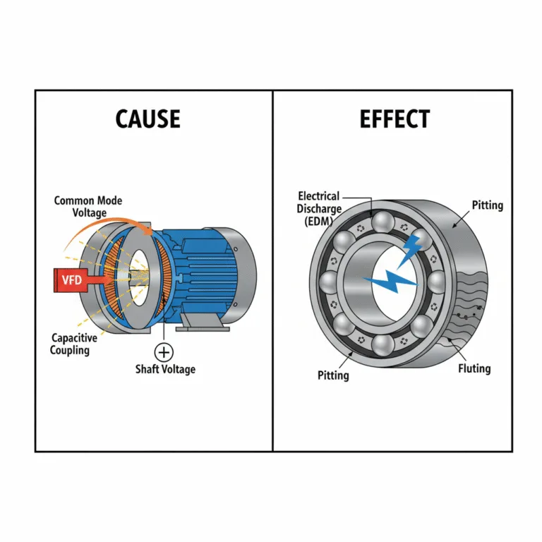
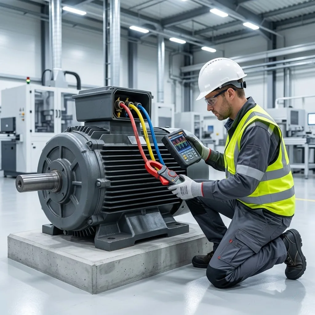
This ranks among the most insidious and destructive failure modes. When motor bearings fail prematurely without apparent mechanical causes, the culprit is often shaft currents generated by the VFD.
- Root Cause: Common Mode Voltage and Capacitive Coupling VFDs simulate sinusoidal AC power using Pulse Width Modulation (PWM) technology. However, their output isn’t a perfectly smooth curve but a series of high-speed switching DC pulses. This asymmetrical waveform generates a “common mode voltage.” This voltage is induced onto the motor shaft through parasitic capacitance (capacitive coupling) between the stator windings and rotor. This energizes the motor shaft. The motor bearings—composed of conductive inner and outer rings and insulating grease—then function as miniature capacitors, continuously charging.
- Failure Mechanism: Electrical Discharge Machining (EDM), Pitting, and Bearing Fluting When shaft voltage accumulates sufficiently to break through the insulating layer of the bearing grease, minute electrical arcs discharge. This process is termed electrical discharge machining (EDM). Millions of micro-arcs per hour create tiny pits and frosting on the bearing raceways and ball surfaces. Over time, these damages coalesce into corrugated grooves resembling a washboard, known as bearing fluting. Once this occurs, the bearing begins to vibrate and produce abnormal noise. The grease degrades due to high temperatures, ultimately leading to bearing seizure and motor burnout. The misalignment between rotor and stator you mentioned exacerbates this effect through magnetic circuit asymmetry, intensifying VFD shaft current bearing damage.
Overheating at Low Speeds: A Common VFD Motor Failure Scenario
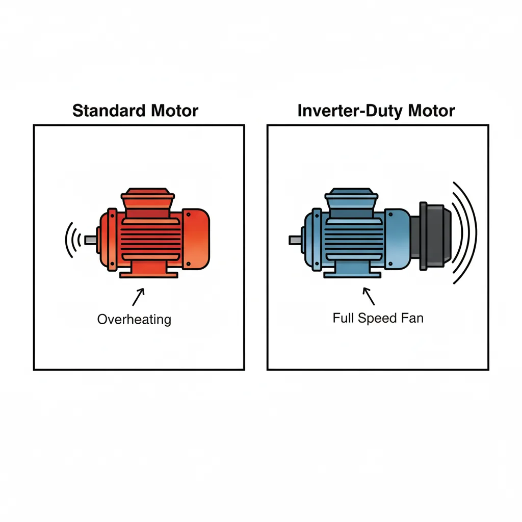
Many applications require motors to operate at low frequencies (e.g., below 20-30Hz) for extended periods—precisely the “danger zone” for standard motors.
- Heat Dissipation Dilemma: Why Low-Speed Operation is Dangerous Standard general-purpose motors (especially TEFC, totally enclosed fan-cooled motors) rely on their shaft-end fans for cooling. The fan speed synchronizes with the motor speed. When a VFD reduces motor speed, the fan’s cooling efficiency drops dramatically. Simultaneously, harmonics in the VFD’s output waveform generate additional heat within the motor windings. As heat accumulates while cooling capacity remains severely inadequate, VFD motor overheating at low speed occurs. Prolonged overheating causes the motor winding insulation to age and become brittle, ultimately leading to interturn or ground short circuits.
- Solution: The Role of Inverter Duty Motors The optimal solution is to use inverter duty motors. These motors typically feature higher-grade insulation materials (such as Class F or Class H) and many models incorporate dedicated, constant-speed cooling fans. This ensures adequate motor cooling under VFD operation, regardless of how low the motor speed becomes.
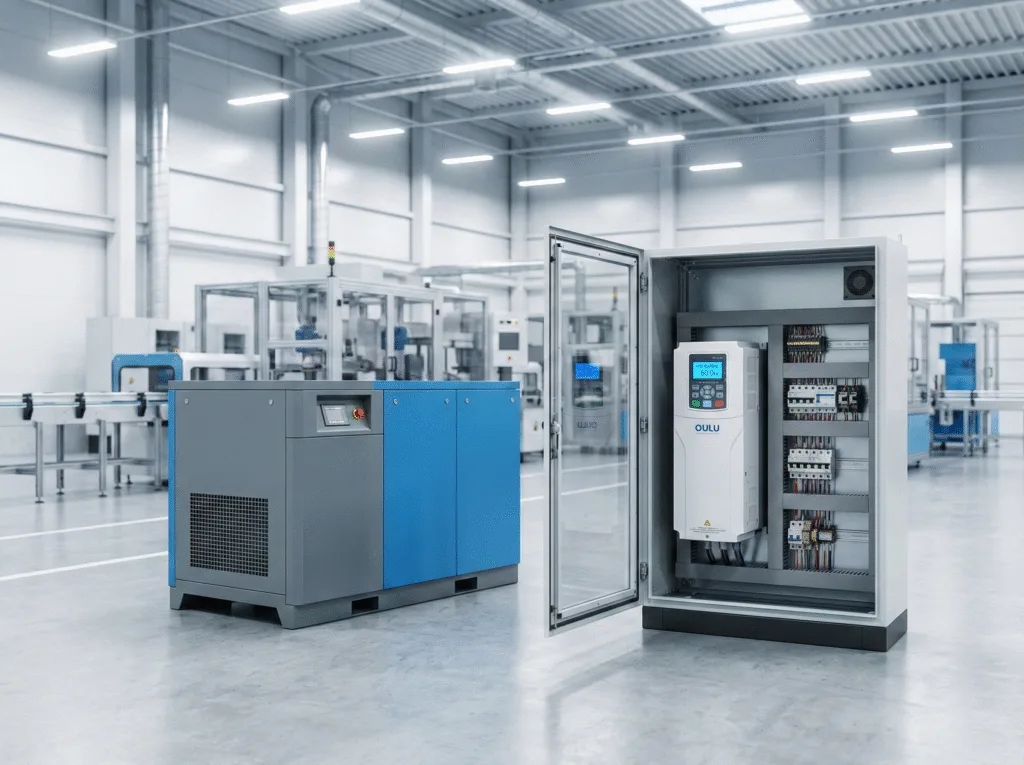
Insulation Breakdown from Long Cables: A Critical VFD Motor Failure Point
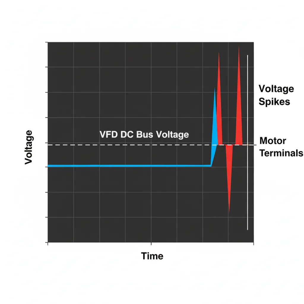
When the cable length between the VFD and motor exceeds certain limits (typically around 30 meters, with risks becoming extremely high beyond 100 meters), an invisible “voltage killer” becomes active.
- Physical Principle: Reflected Wave Phenomenon and Voltage Spikes The high-speed PWM pulses output by the VFD reflect when traveling along the cable to the motor due to impedance mismatches between the VFD, cable, and motor, creating a “reflected wave phenomenon.” These reflected waves superimpose on subsequent pulses, causing peak voltages at the motor terminals to reach 2 to 3 times the VFD DC bus voltage. For a 480V system, this means motors may endure VFD long cable voltage spikes exceeding 1500V. Standard motor insulation systems cannot withstand such prolonged high-voltage impacts, ultimately leading to insulation breakdown.
- Solutions: Filters and Reactors To address long cable issues, protective devices must be installed at the VFD output. A dV/dt filter can slow the rate of voltage rise, while a VFD output reactor or sine wave filter more effectively smooths the output waveform, fundamentally eliminating destructive voltage spikes. Concurrently, using dedicated shielded VFD cable can also mitigate the problem to some extent.
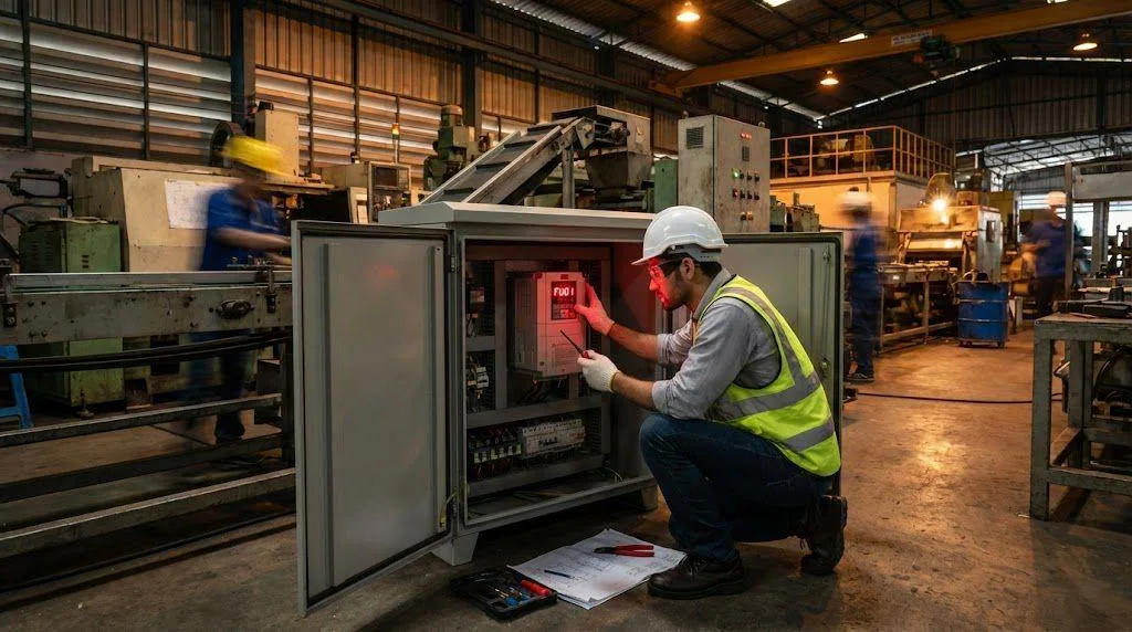
Mechanical & Parameter Issues That Lead to VFD Motor Failure
Beyond purely electrical issues, certain mechanical factors and improper VFD parameter settings can also cause VFD motor failure.
- Mechanical misalignment as a contributing factor: The stator-rotor misalignment you mentioned is a critical mechanical issue. This deviation in motor alignment creates magnetic circuit imbalance, which not only causes vibration and overheating but also significantly exacerbates the shaft current problem discussed earlier, accelerating bearing damage.
- Dead Zone Misconfiguration Leading to Stall: In applications requiring frequent forward-reverse cycling, failure to set a reasonable “Dead Zone” in VFD parameters can cause the VFD to rapidly switch between forward and reverse commands when control signals fluctuate near zero. This results in the motor appearing stationary while actually being in a ‘stalled’ or “micro-vibration” state. In this state, the motor outputs torque but cannot rotate, generating massive currents that cause rapid overheating, ultimately burning out the motor or damaging the VFD.
A Proactive Guide: Preventing VFD Motor Failure
Now that we understand the primary causes of VFD motor failure, targeted measures can be implemented to protect your equipment.
1.Address Bearing Current
For critical applications or large motors, installing shaft grounding rings to provide a safe ground path for shaft currents or using insulated bearings to break the current loop is strongly recommended.
2.Solve Long Cable Issues
Select an appropriate dv/dt filter or VFD output reactor based on cable length and system voltage.
3.Prevent Low-Speed Overheating
Prioritize inverter duty motors. If general-purpose motors must operate at low speeds, install dedicated auxiliary cooling fans.
4.Optimize Installation and Commissioning
Ensure precise motor-to-load alignment. During VFD commissioning, meticulously review all parameters—especially for applications with frequent reversals—and configure appropriate deadband widths.
Conclusion
In summary, VFD motor failure is not an unsolvable mystery. It stems from novel electrical stresses introduced by this advanced control technology. While VFD overcurrent protection is highly sensitive, it cannot fully address multiple slow-onset damage mechanisms like shaft currents, low-speed overheating, and voltage spikes.
By thoroughly understanding the root causes of these failures and implementing proactive protective measures during system design, equipment selection, and installation/commissioning, we can fully leverage the energy-saving and process optimization benefits of VFDs while ensuring long-term reliable motor operation. The key to success lies in treating the VFD and motor as an integrated system, rather than merely a simple combination of two independent components.