How does a VFD Drive work?
What is a VFD? In fact, Variable Frequency Drive (VFDs) is to convert the frequency of the AC power into the motor can be used to adjust the voltage, adjustable frequency of the drive power. It is generally speaking by the rectifier, DC bus, inverter of these three parts.
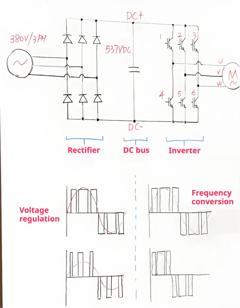
Rectifier:
Rectifier is a bunch of diodes in a bridge circuit, it can be converted to three-phase alternating current into direct current, for example, if your input is a three-phase 380V, then it will be in the back to get a 537V of direct current.
DC bus:
In the rectifier unit is the back of the DC bus, it is actually capacitors, on the one hand, the rectified DC power to become more gentle, on the other hand, also play a role in some of the energy storage.
Inverter:
Next inverter is the core part of the entire inverter, we often hear about the IGBT is actually here, it will also be here to form such a bridge circuit, by controlling the combination of these IGBT conduction, we can realize the direction of the output current and the path of a control, for example, let the 1 and 5 conduction, then the current from the motor’s U-phase into the V-phase outflow, if we let the 2 and 5 conduction, then the current from the motor’s U-phase into the V-phase outflow, if we let the 2 and 5 conduction, then the current from the motor’s V-phase outflow. If we let 2 and 4 conduct, then the current will enter from the V phase of the motor and flow out from the U phase. Further, if we control the triggering of these IGBTs according to a specific period and sequence, then we will get a square wave string like this one in each phase, and by controlling the duty cycle of the square wave, we can realize the regulation of the output voltage, and by controlling the period and length of the square wave, we can realize the regulation of the output frequency. By controlling the period and duration of the square wave, we can realize the adjustment of the output frequency.
This is actually the working principle of the VFD Drives, that is to say, is not the feeling of self can also build a little Variable Frequency Drive (VFDs)
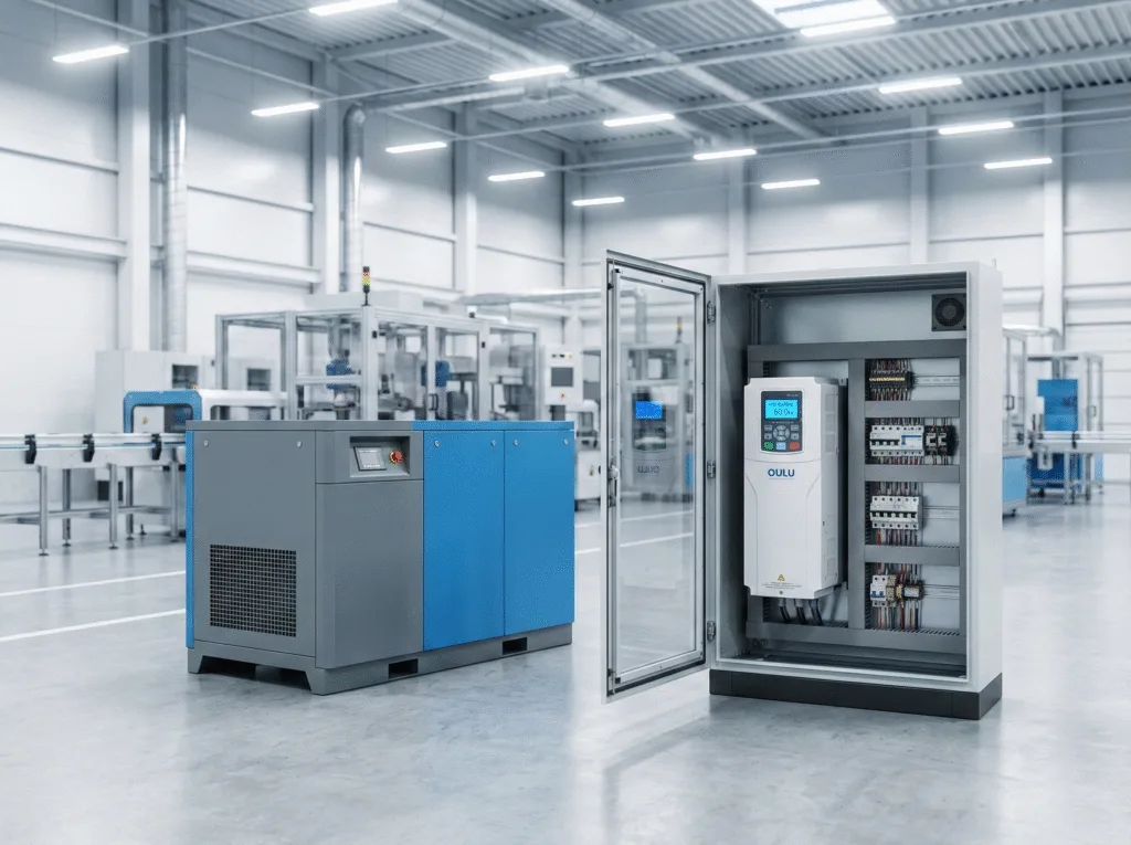
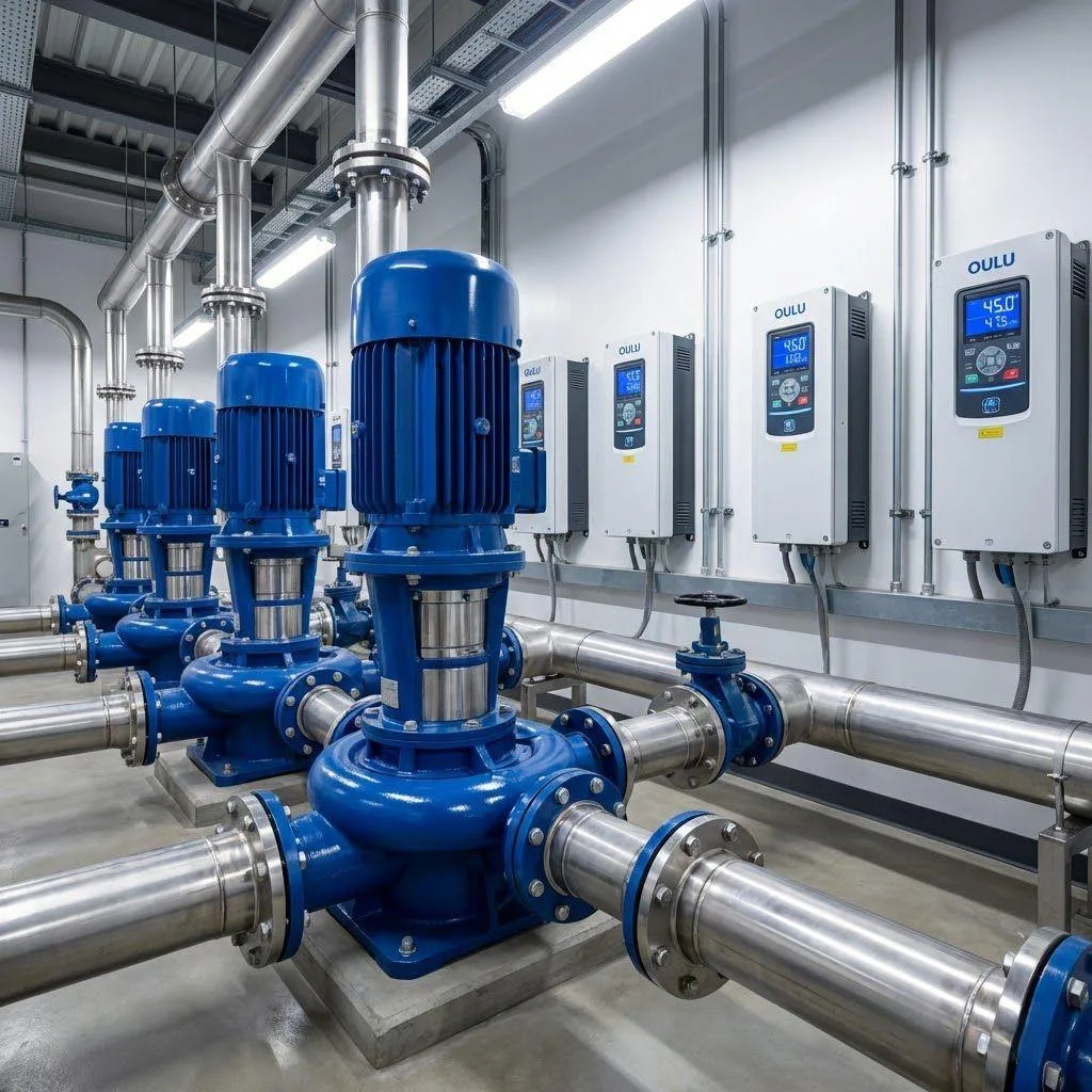
Variable Frequency Drive Motor Control
The main function of the inverter is to control the motor, including motor start/stop, fast/slow, forward/reverse. Frequency converter can change the frequency of AC power, mainly by its internal rectifier and inverter circuit, in the wiring, inverter RST should be connected to the three-phase power supply, and do not need to distinguish the phase sequence.
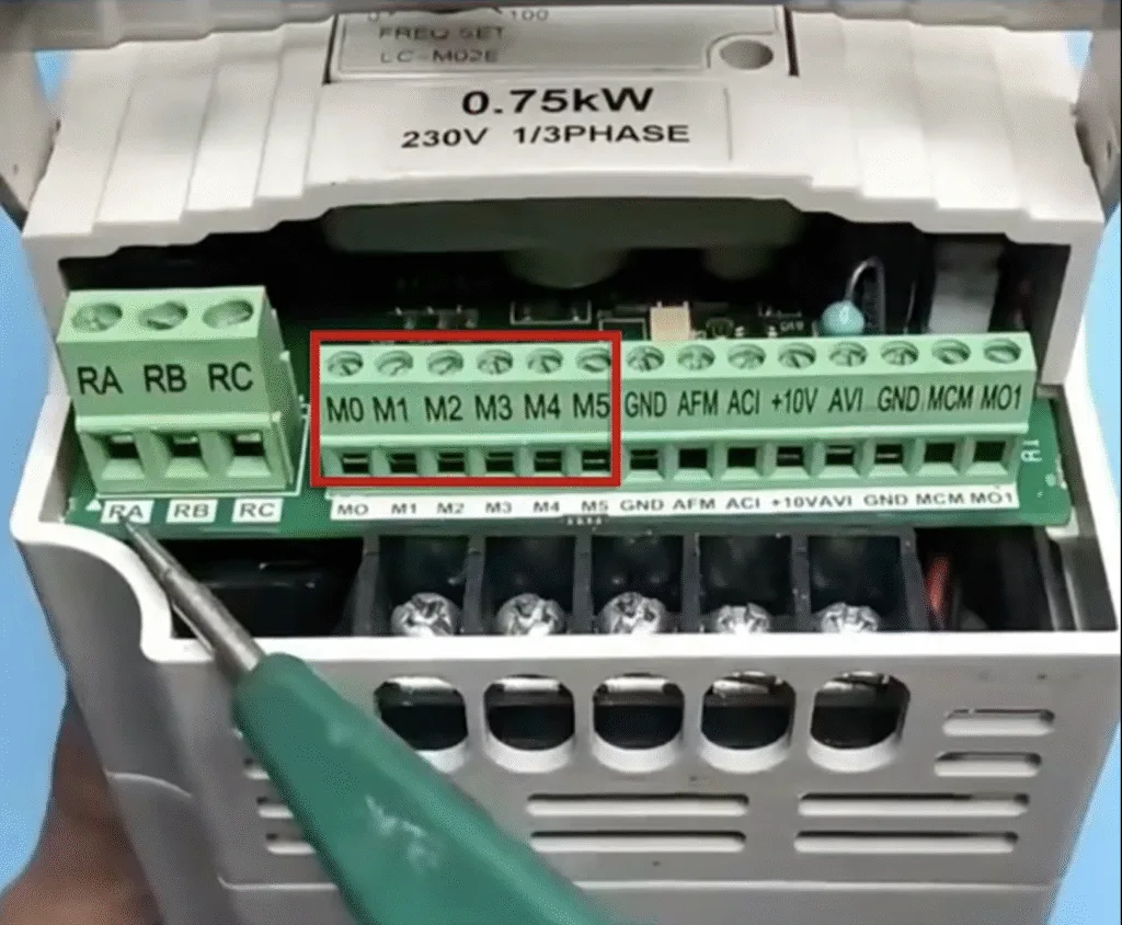
M terminal is used to connect the control switch, where M0 connects to forward rotation, M1 connects to reverse rotation, M2 connects to stop, and M3 and above terminals are usually used for multi-level speed regulation .
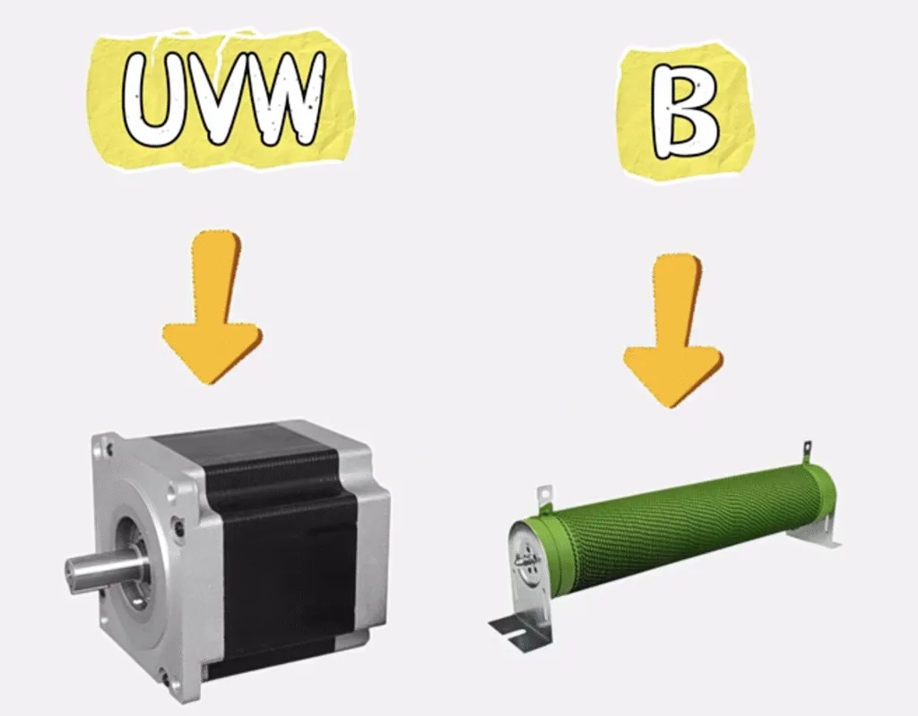
UVW is connected to the motor, and B is connected to the braking resistor to protect the motor from damage when it stops quickly.
Inverter common problems and solutions
1.Overload fault
Mechanical equipment overload, output three-phase imbalance and the inverter internal current detection part of the error overload fault.
- Check whether the motor is hot; if the temperature rise is not high, check whether the preset thermal protection function of the inverter is reasonable. If the inverter has margin, relax the preset value; if not, replace the inverter with larger capacity.
- Check whether the supply voltage and the three-phase voltage on the motor side are balanced; if the voltage on the output side of the frequency converter is balanced, the problem lies in the line between the frequency converter and the motor.
- Check for malfunction. At light load or no load, use the ammeter to measure the output current of the inverter and compare it with the running current value of the display, if the error is large, it means that the tripping is a misoperation.
2.Overheating fault
High ambient temperature, poor ventilation of the inverter, fan jamming or damage, overload, etc..
Check the cooling of the base plate of the inverter, as well as the inverter itself or the control cabinet duct duct is blocked, and should be regular maintenance of the inverter, remove the airway garbage, to maintain smooth ventilation.
3.Ground short circuit fault
motor, cable insulation damage, inverter internal short circuit, multiple motor parallel leakage current. In addition, the longer the cable length, the greater the capacitive current to ground, which can easily lead to tripping.
Can be in the inverter output side and the motor between the series reactor.
4.Overcurrent fault
Starting acceleration time is too short, sudden increase in load, short circuit inverter output, uneven load distribution, inverter and motor capacity mismatch, internal rectifier side or inverter side component damage, power supply phase loss, output disconnection, motor internal faults and ground faults.
- Check the inverter by disconnecting the load first, if there is still fault, the internal components are faulty and need further repair.
- Extend the acceleration time, load distribution design, check the line to prevent interference and mechanical vibration, reduce the sudden change of load.
5.Over-voltage fault
Inverter over-voltage fault refers to the DC bus voltage exceeds the inverter limit value.
- Input side high voltage power supply is too high; easy to trip when deceleration.
- Over-voltage faults include input compensation capacitor, lightning, braking or deceleration time is short, power supply over-voltage and so on.
- Make sure the input power supply voltage is stable first, and then increase the absorption device to reduce the over-voltage factor.
- For overvoltage caused by shock, lightning, compensation capacitor, etc., it can be solved by connecting surge absorbing device in parallel or series reactor.
- Over-voltage fault occurs in the shutdown, related to the intermediate circuit and braking link, can increase the deceleration time or braking resistance.
6.Under-voltage fault
Under-voltage fault refers to the main circuit voltage is too low, such as 220V series is lower than 180V, 380V series is lower than 300V and so on.
Generally due to the lack of phase of the power supply, too many inverters working at the same time or starting at the same time, the current limiting resistor or short-circuit current limiting resistor within the DC circuit of the frequency converter thyristor is damaged, the outside world or the frequency converter interferes with each other.
Check the input part of the frequency converter, make sure that the power supply air switch or contactor contact is good, reduce the contact resistance, confirm that the transformer output voltage is normal, reduce the number of frequency converters starting at the same time, and enhance the anti-interference ability.