How to Program a VFD Like a Pro: Step-by-Step
Just received a new variable frequency drive (VFD) and overwhelmed by the long list of parameters like F0-01, P1-05? Or maybe you’re in the middle of commissioning and worried that a wrong setting could bring everything to a halt? We get it—VFDs can be intimidating at first.
But programming a VFD isn’t about memorizing parameter tables—it’s about understanding the logic behind how each function works. Think of it as a precise instruction set for motor control. This guide avoids dry theory and goes straight to what matters most: the core parameters that affect performance, efficiency, and reliability.
We’ll also cover those small but critical details the manual doesn’t always explain—things that can cost hours of unnecessary debugging. With this guide, you’ll learn to move confidently through VFD menus and use parameter programming as a powerful tool to fine-tune your motor’s speed and torque.
Let’s dive in.
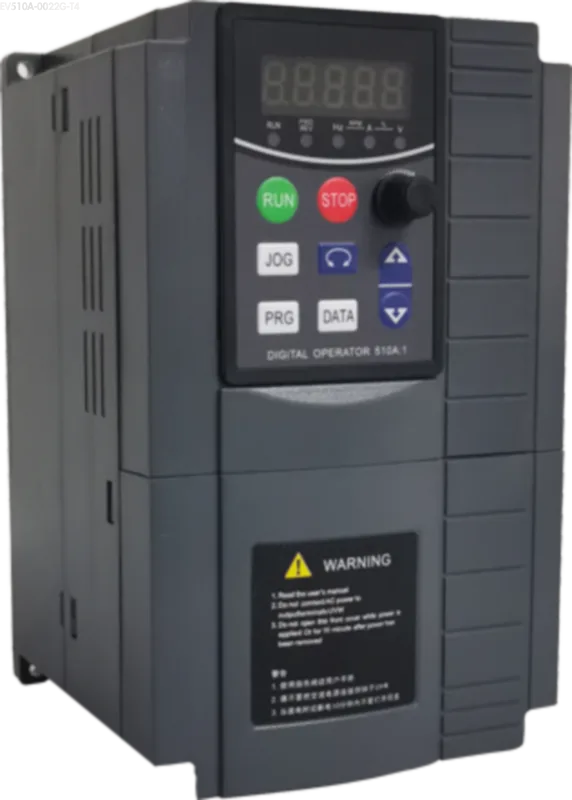
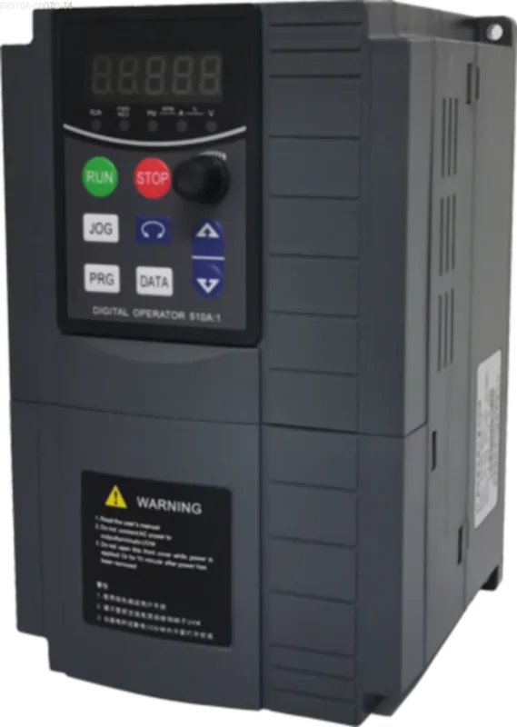
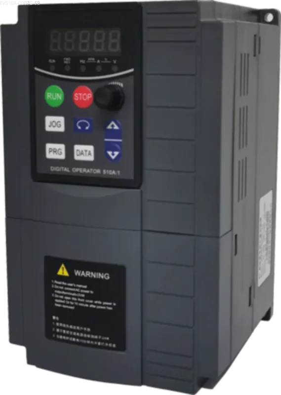
What Is A VFD?
- Precise Speed Control:Adjust motor speed with high accuracy—exactly when and where it’s needed.
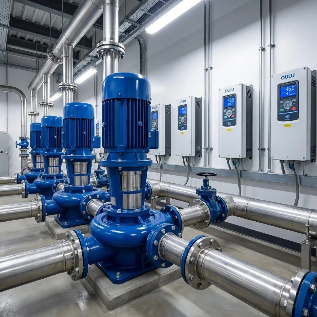
- Industry-Leading Energy Efficiency:Especially in fan and pump systems, reducing speed dramatically lowers energy consumption (since power ∝ speed³).
- Smooth Starting and Stopping:Eliminates current surges, reduces mechanical stress, and extends equipment lifespan.
Basic thinking behind VFD programming
Hold off on jumping into the parameter list! The essence of VFD programming isn’t about blindly entering values—it’s about building a reliable, efficient connection between your drive and motor by understanding the fundamentals and setting parameters accordingly.
As senior drive engineers often say: “Parameters are fixed, but application needs are dynamic.” Before touching a single setting, ask yourself three essential questions:
- What type of load is the motor driving? (Constant torque, variable torque, or constant power?)
- What operations are required? (Start/stop behavior, speed range, acceleration/deceleration time?)
- What environmental or control constraints exist on-site?
These answers directly determine which parameter groups deserve your attention.
According to a report by the IEEE on VFD-related industrial incidents, approximately 34.8% of failures were caused by incorrect basic parameter settings or mismatched load configurations. That’s a powerful reminder: mastering the basics isn’t optional—it’s critical.
At minimum, a solid VFD setup should include:
- Motor parameters: Rated voltage, current, power, frequency, and speed.
- Control mode selection: V/F, sensorless vector, or closed-loop vector.
- Start/stop and ramp settings: Proper acceleration and deceleration times act as a safety buffer, protecting both motor and mechanical transmission systems while avoiding overcurrent trips.
- Protection thresholds: Set limits for overvoltage, undervoltage, overcurrent, overheating, and short-circuits.
Mastering these four fundamentals puts you well on your way to successful VFD programming—and sets the stage for more advanced functions like multi-speed operation, PID control, and reliable troubleshooting.
Key parameters of VFD
Mastering VFD programming starts with a deep understanding of its core parameters. These parameters dictate how the VFD interacts with the motor and directly influence performance, efficiency, and system safety. Below are the essential VFD parameter groups and their primary functions:
1. Motor Rated Parameters
- Voltage: Set the rated voltage consistent with the motor nameplate to ensure constant flux and prevent overheating or magnetic saturation. Incorrect input is a common source of VFD troubleshooting.
- Current: Enter the motor’s rated current. This value serves as a baseline for overload protection—critical for safeguarding both the drive and the motor.
- Power / Frequency / Speed: These define the motor’s characteristics and form the basis for selecting appropriate control algorithms, especially for vector control modes.
2. Control Mode Selection
- V/f Control: A basic mode that maintains a fixed voltage-to-frequency ratio. Ideal for fans, pumps, and other variable torque loads. It’s simple to configure but offers poor low-speed torque.
- Sensorless Vector / Closed-loop Vector: Advanced control modes that decouple torque and flux control. They deliver superior low-speed torque, precise speed regulation, and fast dynamic response. Best suited for constant torque loads like cranes, hoists, and CNC equipment. These modes require accurate motor parameter input.
3. Acceleration / Deceleration Time
- Specifies how long the motor takes to ramp up from 0 to maximum frequency, or ramp down to a stop. Proper ramp times protect mechanical components, prevent overcurrent trips, and support regenerative braking. Setting these correctly is essential for stable operation and energy efficiency.
4. Frequency Limits
- Minimum Frequency: Prevents extended low-speed operation, which can lead to poor cooling, oil flow issues, or motor instability.
- Maximum Frequency: Caps the motor’s speed to stay within safe mechanical limits. This setting must match the motor and load capacity—exceeding it can trigger VFD protection or cause mechanical failure.
5. Protection Parameters
- Overload Protection: Defines the allowable overload threshold (e.g., 110%–150% of rated current). Vital for preventing thermal damage under heavy loads or prolonged operation.
- Overvoltage / Undervoltage: Sets upper and lower DC bus voltage limits. This protects against grid fluctuations and regenerative overvoltage during deceleration.
- Overcurrent: Determines the peak current threshold (often a multiple of rated current) to prevent catastrophic faults such as short circuits. It acts as the last line of defense in drive protection.
6. Special Function Enablers
- Command Source: Specifies the origin of start/stop or control commands—whether from the terminal block, keypad, communication interface, or PLC. Essential for correct wiring and system integration.
- Frequency Setpoint Source: Defines how the VFD receives speed commands—via analog input, digital multi-speed, communication bus, or preset frequency. This directly affects control flexibility and system architecture.
VFD Standard Programming Steps Explained
VFD programming should follow a scientific process to ensure safety and performance. The following are key points of the core programming steps:
1.Pre-Installation Check:
- Verify that the VFD model and specifications meet the requirements of the motor and load.
- Check that the power supply voltage level and phase number match the VFD input.
- Confirm that the installation environment meets the requirements for heat dissipation, humidity, dust, etc., and prepare the necessary space and fasteners (prerequisites for VFD installation).
2.VFD Installation:
- Secure the VFD according to the specifications to ensure good heat dissipation. Strictly follow the VFD drive wiring diagram to complete the main circuit (power input, motor output, ground wire) and control circuit (start/stop signal, frequency command, communication, etc.) wiring.Pay special attention to separating power lines from signal lines, ensuring ground resistance meets requirements (<10Ω) to minimize interference.
3.Power On & Initialization:
- Disconnect all output loads before powering on for the first time. Observe the VFD display for normal operation and no alarm codes. Check the status of the cooling fan. This step is the foundation for subsequent VFD programming and setup.
4.Motor Parameters Setup:
- Core step: Accurately input the motor nameplate data: rated voltage, rated current, rated power, rated frequency, and rated speed. The accuracy of this step directly determines the modeling precision of the VFD for the motor and the effectiveness of protection. Incorrect input is a major cause of VFD failure.
5.Frequency Limits Setting:
- Set the minimum frequency to prevent motor overheating at low speeds or poor lubrication.
- Set the maximum frequency – limits the motor’s maximum speed to protect the motor’s mechanical structure. The range should be set based on the motor’s capabilities and application requirements.
6.Acceleration/Deceleration Time Setting:
- Set the acceleration time and deceleration time (unit: seconds). Reasonable values balance production efficiency, reduce mechanical impact, and prevent overcurrent tripping/overvoltage regeneration alarms. These values should be adjusted and optimized based on load inertia and torque requirements.
7.Control Mode Selection:
- Select the control strategy suitable for the load type and application requirements: Linear V/f – simple, suitable for fans and pumps; Sensorless Vector Control or Closed-Loop Vector Control – high performance, providing excellent low-speed torque and dynamic response, suitable for constant torque loads. The mode selection directly affects the system’s performance limits.
Key Points: After completing the above basic settings, it is essential to perform a no-load test run to observe whether the output current, voltage, and frequency are normal. Only then should the actual load be connected cautiously for load testing. Following standard procedures is critical for efficiently completing VFD programming, ensuring system stability, and minimizing subsequent VFD failures.
Practical Application of Advanced Settings for VFD
Basic operations get a motor running—advanced features make it perform at its best. Master these four powerful functions to elevate your VFD application from functional to exceptional:
1.PID Closed-Loop Control
- Function: Automatically adjusts motor output to maintain a process variable (e.g., pressure, temperature, flow) in line with a target value.
- Implementation Tips:
- Enable PID control in the VFD menu.
- Select the appropriate feedback signal (analog or digital).
- Configure the setpoint input method.
- Start tuning with proportional gain (P) to improve responsiveness.
- Then adjust integral time (I) to eliminate steady-state error.
- Use derivative gain (D) cautiously to suppress overshoot.
- Always set output limits and enable feedback filtering to ensure system stability.
2.Multi-Speed Operation & Programmed Sequences
- Function: Allows the motor to switch between fixed speeds or run automatically according to predefined timing sequences.
- Setup Notes:
- Activate multi-speed mode in the drive.
- Define target frequencies for each speed step.
- Assign external terminals or internal timers to select speed profiles.
- Pay special attention to transition logic between speeds and set smooth acceleration/deceleration times to prevent mechanical shock.
3.PLC Integration & Communication
- Function: Seamlessly connect your VFD to external automation systems (PLCs, DCS) for remote control and real-time data exchange.
- Key Configuration Steps:
- Choose the correct communication protocol (Modbus, CANopen, EtherCAT, etc.).
- Set the correct slave/station address.
- Map control words and feedback parameters accurately.
- Ensure correct physical wiring (shielded cables, grounding, terminations).
- This enables remote monitoring, centralized control, and smart factory-level automation.
4.Braking & Regenerative Energy Management
- Function: Manages the excess energy generated during deceleration or when handling high-inertia or descending loads.
- Best Practices:
- Experiencing extended braking time? → Activate the internal braking resistor (if supported).
- Match the braking resistor’s power rating to system needs.
- If deceleration causes overvoltage or instability → Adjust deceleration ramp time.
- For heavy-duty cycles or high-energy release → Use external braking units or consider regenerative feedback solutions.
VFD Troubleshooting ? Focus on These 3 Critical Factors First
1.Classic Three-Fault Triggers
- Trips during startup?
- Extend acceleration time.
- Check for mechanical binding or high inertia.
- Verify motor nameplate data—especially rated current.
- Measure insulation resistance of the motor and wiring.
- Trips during operation?
- Inspect for short circuits, motor overload, or internal motor faults.
- Troubleshooting Steps:
- Increase deceleration time.
- If high load inertia is involved, verify that the braking resistor or regenerative braking function is enabled and properly configured.
- Measure supply voltage—abnormal grid spikes may be a factor.
- Checkpoints:
- Inspect incoming power supply: is there a missing phase or loose terminal?
- Measure actual input voltage.
- Check the condition of breakers, switches, and contactors.
- Ensure the undervoltage threshold is correctly set in the VFD.
2.Command Failures
- Confirm the command source (terminal, keypad, or communication).
- Check start/stop signal wiring and input voltage levels.
- Clear any fault locks that may prevent startup.
- Verify frequency reference source (analog, preset, or communication).
- Check signal cable integrity and ensure scaling/range matches.
- If using PLC: confirm communication status and data mapping.
- Swap two motor phases or enable direction inversion in parameters.
- Check for “reverse prohibition” or locked direction settings.
3.Performance Abnormalities
- Check if you’re using basic V/f mode—consider enabling torque boost (with caution).
- For better low-speed performance, switch to sensorless vector control.
- Run motor auto-tuning or parameter identification routines.
- Are the motor parameters correctly set?
- Is the mechanical load heavier than expected?
- Investigate for excessive friction or mechanical misalignment.
- Inspect shielded cable quality and grounding.
- Confirm baud rate, station ID, and communication format match.
- Check for excessive cable length or external electrical noise.
- “Alarm codes are clues—not just errors. Always start with the display prompt.”
- “Resetting parameters to defaults + following a structured setup solves 90% of issues. (Just remember to back up first!)”
- “Segment the problem logically: Is it a signal/input issue? A load mismatch? Or a parameter/config error? Narrow it down quickly and methodically.”
- “Leverage drive software tools for real-time data monitoring. Solid training + hands-on experience turns every fault into valuable know-how.”
Conclusion
Mastering VFD programming is not out of reach. The key lies in clearly understanding the logic behind VFD parameters—they are not codes, but the “keys” that enable you to precisely control the VFD drive motor. From the fundamentals of VFD installation and VFD drive wiring, to motor parameter settings, selecting VFD control modes, and advanced applications like PID Control, every step directly impacts the performance and safety of VFD motor control.Remember standard procedures, consult manuals, and prioritize accumulating VFD troubleshooting experience—these will help you efficiently tackle real-world VFD application challenges and make the variable frequency drive the intelligent core of a stable and efficient drive system! This VFD training journey’s destination is for you to become the absolute conductor of motor rhythm!