Shielded vs Unshielded VFD Cables: Key Differences Explained
Engineering Insights: Shielded vs Unshielded VFD Cables — Practical Differences You Can’t Ignore
Hello everyone. Today we’ll dive into a frequently overlooked but highly consequential topic in industrial power systems — the real-world differences between Shielded and Unshielded VFD Cables. While they may seem similar at first glance, their behavior in high-frequency, high-power environments tells a very different story — especially when it comes to VFD cable overvoltage, interference, and grounding safety.
1.Structural Differences of VFD Cables: It’s More Than Just Copper
The difference between Unshielded and Shielded VFD Cables goes beyond appearance. Unshielded types typically include only three power conductors. In contrast, shielded cables wrap these cores in a copper mesh or metallic armor layer, which is grounded for vfd cable emi reduction. While this may seem like a small structural tweak, its electrical consequences are significant.
2.Capacitance Behavior: Why Shielding Changes the Game
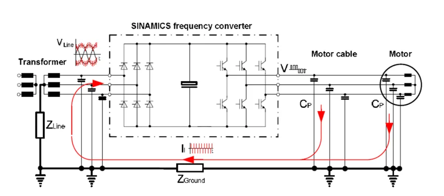
In Unshielded VFD Cables, only three inter-phase capacitive couplings form among the three conductors. But with Shielded VFD Cables, you introduce an additional three line-to-ground capacitive paths — one from each phase conductor to the grounded shield.
That’s six coupling paths in total — and more capacitance means more surge current under transient conditions. These peak voltages, caused by switching harmonics, can reach 2000–2500V at the motor end for a 100-meter cable, and trigger severe vfd overcurrent events or insulation stress.
3.VFD Cable Length Limitations: The Hidden Design Constraint
Every reputable VFD manufacturer provides a clear vfd cable length limit:
- Unshielded VFD Cables: Typically allowed up to 100–150 meters
- Shielded VFD Cables: Limited to 50–75 meters maximum
Why the dramatic difference? Because added shield capacitance doubles the capacitive charging/discharging current. This increases the risk of vfd overvoltage faults, sharp current spikes, and unwanted tripping during motor startup — all extremely difficult to diagnose because these events occur within microseconds.
4.Reflected Wave Overvoltage: A Killer for IGBT and Motor Windings
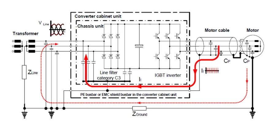
With Shielded VFD Cables, the presence of extra capacitance and the skin effect intensifies voltage rise times. This accelerates reflected wave phenomena, resulting in voltage doubling at the motor terminals.
These conditions can easily cause vfd dc bus overvoltage, false trips, or worst-case — IGBT failure due to fast transients. Without proper vfd cable grounding and filtering, these effects can cascade into costly downtime.
Real-World Wiring Tips for Safer VFD Cable Installation
1.Prefer Unshielded Cables + Increase Cable Tray Spacing
Following Siemens’ European EMC standard, maintaining >22cm of separation between power and control trays minimizes cross-talk. Our field-tested recommendation is ≥40cm distance for reliable vfd cable interference mitigation without the need for shielded cable.
2.Add Output Reactors or VFD Filters for Shielded Installations
If shielding is necessary, always pair it with a VFD output reactor or common-mode choke to suppress harmonics and reduce dv/dt peaks.
Warning: When using filters, always connect the capacitive end to the motor side and the inductive end to the VFD. Incorrect connection will destroy your IGBT units instantly upon energizing.
3.Control VFD Cable Length Aggressively
Even for Unshielded VFD Cables, limit the run to <150 meters. Use lower carrier frequencies, increased conductor cross-section, or install output reactors for runs nearing the threshold.
Conclusion: VFD Cables Are a System Decision, Not a Commodity
Choosing between Shielded and Unshielded VFD Cables isn’t just a matter of budget or EMI concern. It’s a systems-level decision that influences motor reliability, VFD health, fault rates, and even electromagnetic compliance.
Shielded cables are not “safer by default” — they require shorter runs, more precise grounding, and harmonic mitigation strategies. On the other hand, unshielded options — when installed with proper spacing and grounding — can achieve stability over longer distances without introducing new failure modes.
Understanding this distinction is critical for engineers tasked with designing or maintaining reliable VFD Drives systems. Don’t let a simple cable selection become your next hidden liability.