VFD Motor Damage: 8 Harmful Effects on Standard Motors
Introduction — Why Standard Motors Suffer Under VFD Operation
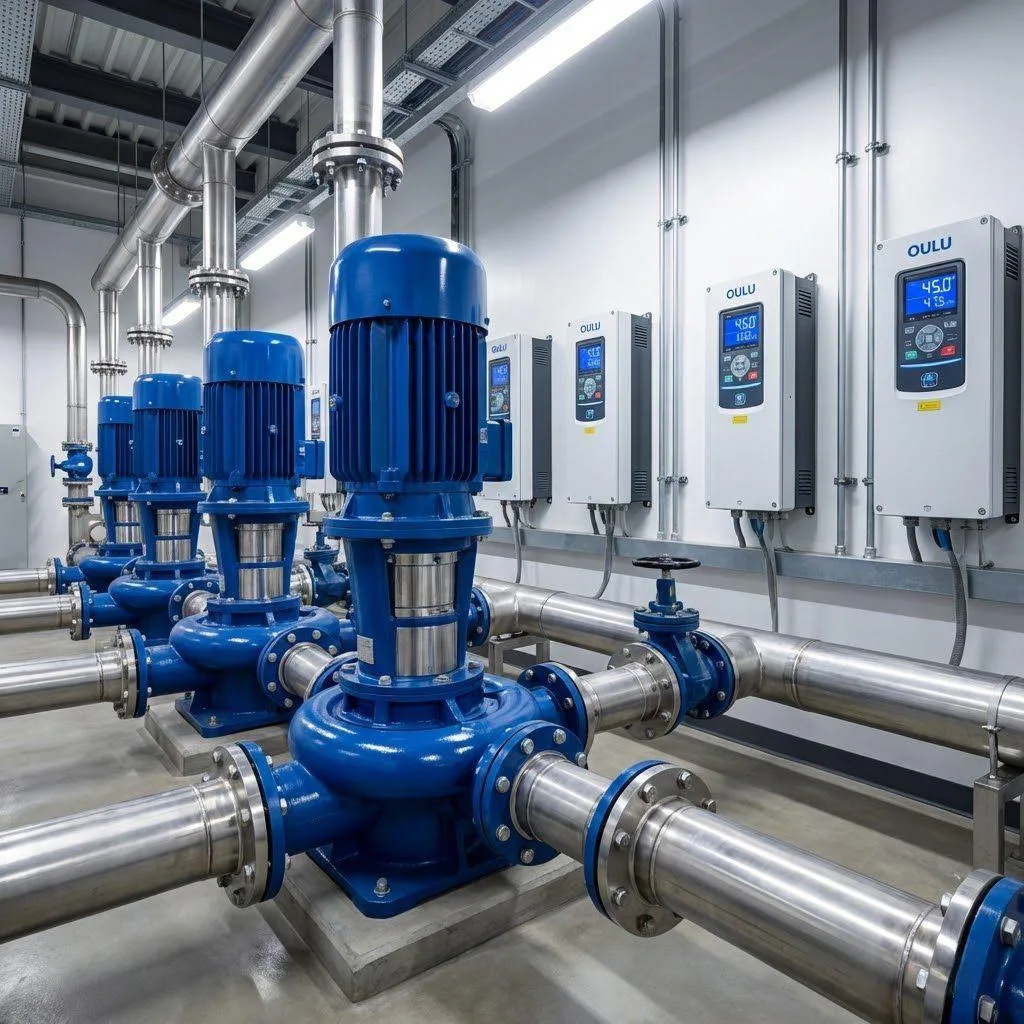
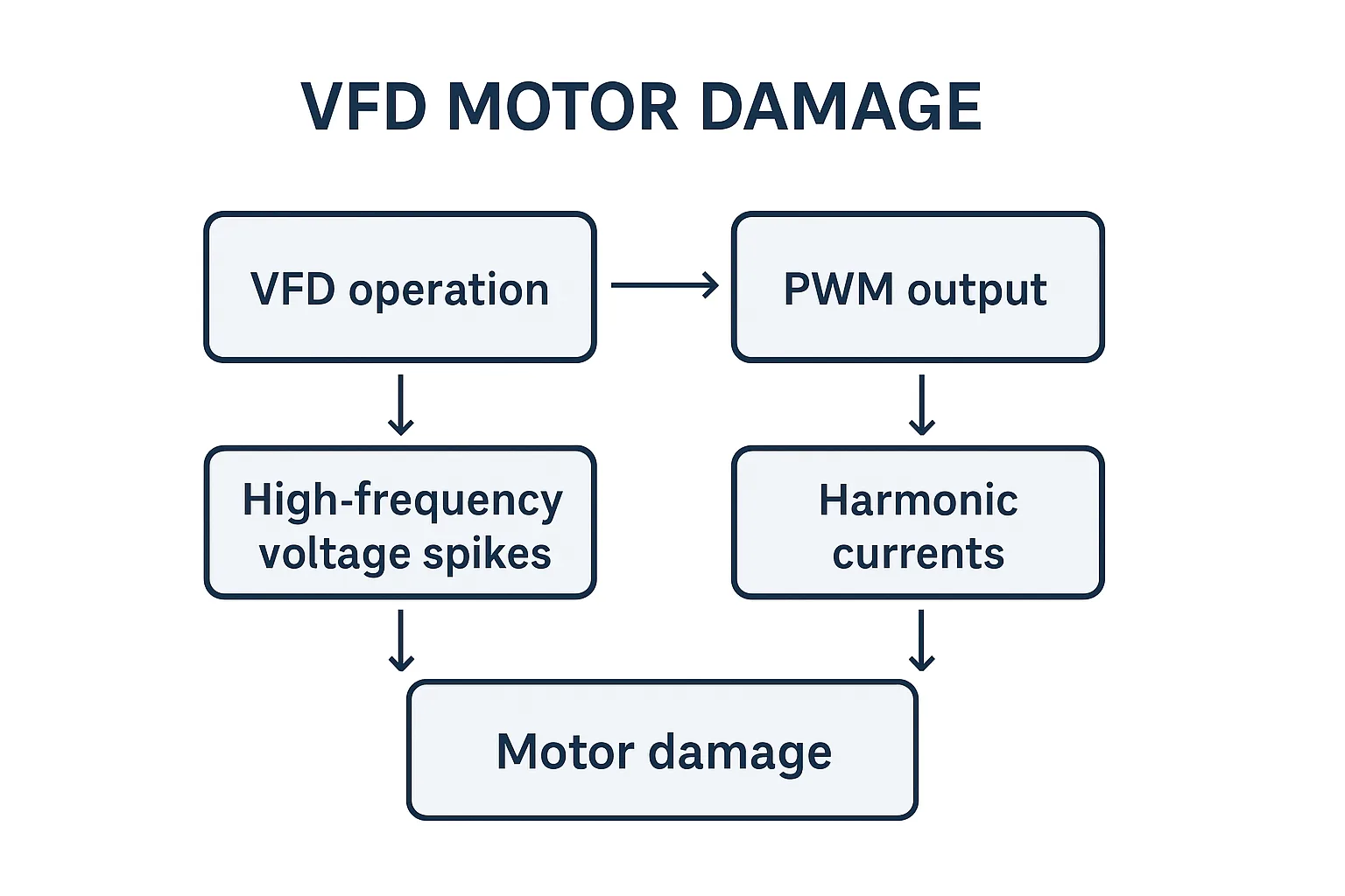
In most industrial applications, standard three-phase induction motors are widely used with VFD drives because they’re inexpensive and easily available. However, the VFD output waveform isn’t a smooth sine wave — it’s a PWM (Pulse Width Modulation) square-like waveform filled with high-frequency harmonics and voltage spikes.
These harmonics can severely impact motor insulation, bearings, and winding temperature, eventually leading to VFD Motor Damage.
While standard motors can work in light or general-purpose conditions, applications requiring high precision, frequent acceleration, or low-speed torque demand inverter-duty motors.
Eight Common Causes of VFD Motor Damage
No. | Cause | Mechanism | Typical Result |
|---|---|---|---|
1 | PWM voltage spikes | Reflected wave amplifies at cable end | Inter-turn or phase-to-phase short circuit |
2 | Insulation aging | Harmonics accelerate dielectric breakdown | Reduced motor lifespan |
3 | Bearing currents | Common-mode voltage induces shaft current | Fluting, lubrication failure |
4 | Parasitic capacitance | High-frequency discharge through oil film | Bearing pitting, surface erosion |
5 | Harmonic heating | High/low-order harmonics raise copper and iron losses | Motor overheating |
6 | Torque ripple & vibration | Harmonic torque pulsation | Mechanical resonance, loosened housing |
7 | Poor cooling at low speed | Reduced fan speed at <15 Hz | Thermal overload, winding burnout |
8 | Excessive high-frequency run | >75 Hz continuous operation | Bearing fatigue, insulation stress |
Hidden Mechanisms Behind VFD Motor Damage
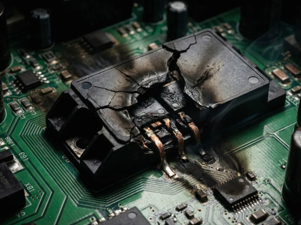
1.High-Frequency Voltage Spikes → Insulation Breakdown
PWM output creates reflected waves, especially on long cables, producing several-kilovolt spikes. Standard motors (typically <1000 V insulation rating) are easily damaged.
2.Bearing Current and Electrical Erosion
Common-mode voltage forms a capacitive coupling between rotor and frame, causing discharge through the bearing — known as electrical discharge machining (EDM) or fluting.
Check for “wash-board” bearing track marks as a sign of EDM.
3.Harmonic Heating (Copper and Iron Losses)
Harmonics induce eddy currents in both stator and rotor, creating extra copper and iron losses.
At low-speed heavy loads, this results in additional torque ripple, reducing efficiency and accelerating wear.
The Relationship Between Frequency and Cooling Efficiency
When the VFD operates at low frequency (<15 Hz), the motor’s internal fan rotates too slowly to provide sufficient airflow. To prevent overheating, engineers should:
- Install an external forced-cooling fan
- Use an inverter-duty motor with independent ventilation
- Avoid continuous low-speed full-load operation
Frequency Range | Cooling Efficiency | Recommendation | ||
|---|---|---|---|---|
0–15 Hz |
|
| ||
15–50 Hz | Normal | Self-cooling acceptable | ||
>75 Hz |
| Monitor bearings & temperature |
How to Minimize VFD Motor Damage Risks
- Use inverter-duty motors (rated 1600–2000 V insulation)
- Install dV/dt filters or output reactors to suppress voltage spikes
- Apply shielded cables with double-end grounding to reduce EMI
- Add shaft grounding rings to eliminate bearing current flow
- Set proper carrier frequency and accel/decel time
- For long cables, assess VFD cable parasitic capacitance
- Limit high-frequency operation to ≤75 Hz to avoid stress damage
Conclusion — Standard Motors Aren’t Always Safe on VFDs
While standard motors can technically operate with a VFD, they’re not designed to handle harmonic stress, shaft currents, or voltage spikes.
These issues don’t always appear immediately — but over months of operation, they cause irreversible deterioration.
Best practices:
- Use standard motors only for light-duty, non-critical applications.
- For heavy, precise, or continuous adjustable-speed use, select VFD-rated motors.
- If replacement isn’t possible, at least add output filters and bearing protection systems.