What Are the Three Types of VFD?
Introduction – What Does“VFD”Mean in Electrical Systems?
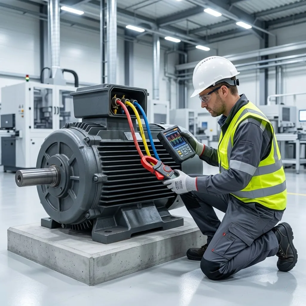
Variable Frequency Drive (VFD) Essentially an electrical power frequency converter: it converts AC power into DC power and then back into AC power, reshaping the power supply into variable frequency/voltage output (range 0-650Hz), thereby achieving VFD motor control stepless speed regulation. define variable frequency drive refers to this type of semiconductor regulation system (also known as adjustable frequency drive), which belongs to the electrical category of types of variable speed drives. Its core value lies in eliminating 80% of motor startup impact current, enabling industrial loads to precisely match operational requirements.
Type 1 – Voltage Source Inverter (VSI) VFD
Working Principle
One of the core topologies of modern variable frequency drives (VFDs), its essence lies in converting rectified DC power (maintained at a stable voltage by capacitors) into high-frequency pulse sequences via PWM VFD technology; The variable frequency drive controller adjusts the pulse width and interval ratio to dynamically synthesize the required voltage (0-480V) and frequency (0-650Hz) in the form of a sine wave equivalent, thereby achieving seamless continuous regulation of the VFD motor control.
Advantages
- System efficiency >92% (based on Si-IGBT inverter modules)
- Output waveform distortion rate <5% (compliant with IEEE 519 standard)
- VFD speed control accuracy up to ±0.5% (compared to ±5% for hydraulic speed control)
- Compatible with standard 380V three-phase motors without modification
Disadvantages
- Grid voltage tolerance is only ±10% (exceeding this range may trigger under-voltage protection)
- High-frequency PWM may cause motor bearing current risks (requires common-mode filter suppression)
- Input current harmonic THDi > 35% (requires an external 12% input reactor)
Application Scenarios
As a typical representative of the variable voltage variable frequency inverter, it dominates the following fields:
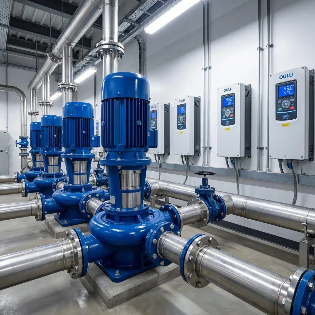
- HVAC systems: Chilled water pump frequency from 50Hz to 35Hz, energy consumption ↓42%
- Centrifugal fans: Full-open damper + variable frequency speed control, comprehensive energy savings rate ≥28%
- Water supply pump stations: Flow adaptive regulation in constant pressure mode (0-100Hz response)
Type 2 – Current Source Inverter (CSI) VFD
Working Principle
The CSI variable frequency drive operates in a manner analogous to a voltage-source VFD, functioning like a helmsman guiding a river of energy. The rectifier side uses inductive energy storage to replace capacitors, establishing a stable direct current source (rather than a constant voltage), which is then directed through thyristor switching technology to control the current flow.
The output rectangular current waveform is precisely regulated by the VFD control system in terms of amplitude (rather than PWM pulse width), making it particularly suitable for the startup requirements of high-inertia loads such as ball mills.
Advantages
- Supports four-quadrant operation (100% energy feedback to the grid)
- Withstands 200% current surges (instantaneous fluctuations in metallurgical arc furnaces)
- Natural short-circuit resistance (inductor suppresses di/dt)
- Power range: 0.5–50 MW (far exceeding VSI’s 0.75 MW limit)
Disadvantages
- 40% larger volume than VSI (inductance components occupy space)
- Requires a dedicated motor for variable frequency drive motor control (ordinary motors are prone to magnetic saturation)
- Output harmonics > 25% (mandatory configuration of 12-pulse rectifier)
- Minimum speed limit of 15 Hz (lower than VSI’s 5 Hz)
Application Scenarios
Preferred choice for large-scale heavy industry core power sources:
- Mine compressors: Regenerative braking for 2000 kW-class screw compressor units
- Metallurgical rolling mills: Torque pulsation suppression (fluctuation <3%)
- Cement tube mills: Starting torque up to 300% of rated value
Type 3 – Pulse Width Modulated (PWM) VFD
Working Principle
As the mainstream solution with a market share of over 85%, pulse width modulation VFD is like a mosaic artist in the field of power electronics—it uses IGBT modules to switch the DC bus voltage at an ultra-high speed of 3-15 kHz, generating microsecond-level pulse sequences with precise and controllable widths.variable frequency drive inverter algorithm real-time calculates pulse width combination strategies to make the output waveform infinitely close to a sine curve (THD < 5%), achieving seamless regulation of motor torque/speed.
Advantages
- pwm vfd Optimal output waveform quality (compared to CSI rectangular wave/VSI step wave)
- vfd speed control Accuracy up to ±0.1%(Vector control mode)
- Motor operating noise ≤65 dB (carrier frequency adjustable)
- Compact power density up to 2.8 kVA/kg (4 times higher than CSI)
Disadvantages
- Generates 3–150 high-frequency harmonics (requires a 12% input reactor to suppress THDi <8%)
- Complex electromagnetic compatibility design (mandatory installation of RFI filters)
- dv/dt stress accelerates motor insulation aging (>5 kV/μs)
Application Scenarios
The absolute leader in precision speed control:
- Building automation: Elevators Vector drive Floor leveling accuracy ±3 mm
- Food packaging lines: Servo synchronous control response time <2 ms
- CNC machine tools: Spindle speed 0-6000 rpm stepless switching
Comparison Table of the Three VFD Types
Features | VSI-VFD | CSI-VFD | PWM-VFD |
|---|---|---|---|
Control mode | Constant voltage source + PWM drive | Constant current source + phase control | Constant voltage source + high-frequency PWM drive |
Core Components | Rectifier Capacitor Assembly IGBT Module | DC Reactor Thyristor | SiC-IGBT Module DSP Controller |
structural complexity | ⭐⭐️ | ⭐️⭐️⭐️⭐️ | ⭐️⭐️⭐️ |
Suitable motors | Standard Induction Motor | High-Inertia Motor | Induction / Permanent Magnet Synchronous Motor (PMSM) |
Power range | 0.75-750kW | 500kW-50MW | 0.37-630kW |
Speed response | 5-20ms | 50-100ms | 0.1-5ms (vector control) |
Typical applications | HVAC water pumps | metallurgical rolling mills | CNC spindles |
How to Choose the Right VFD Type for Your Application
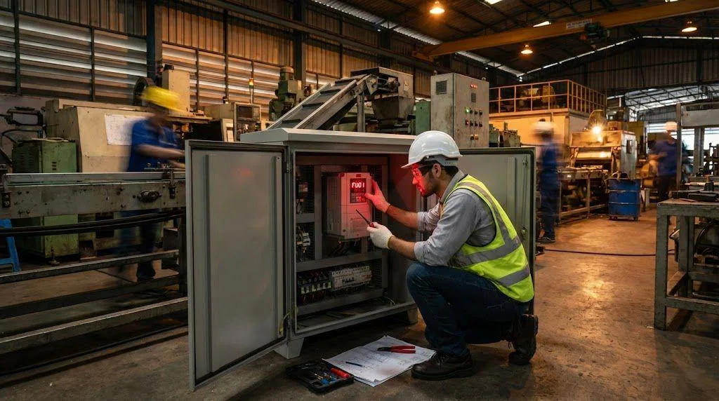
Selection criteria are based on load characteristics and power requirements: Variable torque loads (fans/pumps) should prioritize PWM-type HVAC VFDs (50Hz → 40Hz energy savings > 35%, standard for HVAC drives), whose VFD drives seamlessly integrate with industrial-standard three-phase VFD systems (380V three-phase coverage > 90% of applications); impact loads such as crushers require CSI topology (capable of withstanding 300% current surges for 2 seconds). For single-phase 220V legacy equipment, VFDs for single-phase motors are available only up to 3.7 kW (must include a virtual three-phase module); otherwise, motor retrofitting is recommended.VFD installation must meet the following requirements: 1) Transformer capacity > VFD power × 1.25 (harmonic THDi < 8%); 2) Cabinet cooling clearance ≥ 30 cm (thermal loss 3% × power); 3) The VFD system must be equipped with an EMC filter (conducted interference ≤ 55 dBμV). For high-dynamic response applications (e.g., CNC spindles), SiC-IGBT PWM vector control is recommended. For heavy-load start/stop conditions, a thyristor CSI + permanent magnet motor (NdFeB material with temperature resistance ≤ 150°C) combination is recommended to release maximum torque.
Conclusion – VFD Types and Their Role in Modern Automation
Three types of variable frequency drive (VFD) architectures each serve distinct functions: VSI uses voltage precision to control centrifugal pumps, CSI employs current rigidity to manage rolling mills, while PWM utilizes high-frequency pulses to refine CNC precision—all fundamentally achieving the revolution of VFD motor control by reconfiguring electrical energy waveforms.
Incorrect selection can lead to double costs: mismatching variable frequency drive components (e.g., using VSI for crushers) can cause system efficiency to drop by 25%; conversely, precisely deployed vfd drive panels (integrated with EMC filtering and cooling systems) can reduce HVAC equipment maintenance costs by 40%.Addressing the fundamental distinction between VSD and VFD: Mechanical variable speed drives (VSD) are like manual gearboxes, while VFD control is akin to a CVT continuously variable transmission—using semiconductor-level precision regulation to establish the foundation for energy efficiency. When every motor in a factory is driven by a compatible VFD, the industrial network transforms into a real-time responsive intelligent organism.