3 Common PLC to VFD Connection Methods Explained
There is a subordinate relationship between a PLC (Programmable Logic Controller) and a VFD (Variable Frequency Drive). Both can be used to control motor operations, but they serve different roles. The PLC is a programmable control unit, while the VFD is typically one of the devices managed by the PLC.
Compared to a VFD, a PLC has a broader range of functions. It can control not only motors but also various other types of equipment. It offers wider application coverage and higher control precision. A VFD cannot be programmed; it simply adjusts motor speed by changing the frequency and voltage of the power supply. The output frequency of a VFD can be fixed or dynamically regulated by the PLC.
The PLC can be programmed to control electrical devices, perform logic operations, process data, and handle communication tasks.
Communication between the PLC and the VFD typically follows the USS serial communication protocol, which operates on a master-slave principle. On a single bus, one master and up to 31 slave devices can be connected. The master sends messages to select which slave to communicate with. Slaves cannot initiate communication or talk to each other directly.
There are generally three common methods for connecting a PLC to a VFD:
1. Analog Signal Control
The PLC outputs an analog voltage (0–5V) or current (4–20mA) via its analog output module. This signal is fed into the VFD as its input to control the output frequency. This method is easy to wire but requires matching the PLC’s output impedance with the VFD’s input. Analog modules are usually more expensive, and a voltage divider may be needed to ensure signal compatibility. Additionally, power and control wiring should be routed separately to minimize electrical noise.
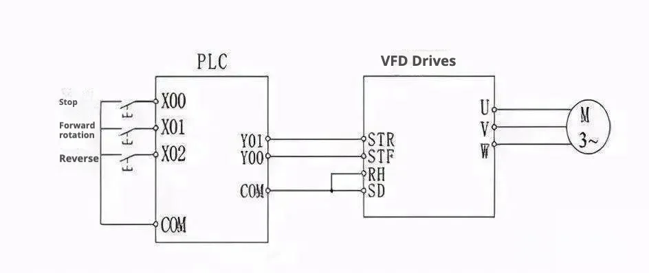
2. Digital Signal (Discrete I/O) Control
The PLC’s digital outputs can directly control the VFD’s digital input terminals. This approach is straightforward and offers strong noise immunity. It can be used to control start/stop, forward/reverse rotation, jog operations, speed level selection, and acceleration/deceleration time. However, it only supports step-based speed control (not continuous). If relays are used, poor contact might lead to malfunction. If transistors are used, their voltage and current ratings must be considered to ensure system reliability. Furthermore, when designing the VFD input circuit, special care should be taken if inductive loads (like relays) are used, as switching may produce surge currents that can cause the VFD to misbehave.
3. RS-485 Serial Communication
Most Siemens VFDs are equipped with an RS-485 interface (some also support RS-232). RS-485 uses a two-wire setup and is designed for industrial environments. A single RS-485 bus can connect up to 30
VFDs. The PLC can communicate with specific drives by address or via broadcast commands. In this setup, the PLC acts as the master, and the VFDs operate as slave devices responding to instructions.
Pros and Cons of the Three PLC-VFD Connection Method
Control method | Advantages | Disadvantages | Typical application scenarios |
|---|---|---|---|
Analog Control | ✅ Continuous stepless speed control ✅ High control accuracy (±0.1%) ✅ Supports complex closed-loop control (PID) | ❌ Poor interference resistance (signal attenuation) ❌ High wiring costs (shielded cables required) ❌ Slow response time (50–100 ms) | Constant pressure water supply, temperature regulation, precision tension control |
Switching Control | ✅ Strong anti-interference ✅ Fast response (<50ms) ✅ Low cost (standard cable) | ❌ Only discrete speed control (limited speed settings) ❌ Cannot be finely adjusted ❌ Poor scalability (limited by the number of terminals) | Multi-speed fan control, conveyor belt start/stop, simple pump control |
Communication Control | ✅ Ultra-high precision (±0.01%) ✅ Real-time monitoring of equipment status ✅ Centralized control of multiple devices ✅ Minimal wiring (single network cable) | ❌ High cost (modules + protocol licensing) ❌ High technical barriers (requires protocol configuration) ❌ Network failures cause system-wide shutdowns | Smart factories, multi-machine collaborative production lines, big data monitoring platforms |
Summary: Best Ways to Connect PLC and VFD
- Analog → “High precision but delicate”: Suitable for precise continuous regulation, but susceptible to interference and long distances;
- Digital → “Rugged and cost-effective”: The king of interference resistance, the first choice for low cost, but don’t expect precise control;
- Communication → “Smart but expensive”: The core of the factory of the future, trading money for efficiency and precision.
Golden Rules for Selection:
- Simple scenarios (fewer than 3 devices) → Switching control;
- Precision regulation (temperature/pressure closed-loop) → Analog control;
- System integration (more than 5 devices + monitoring required) → Go for communication control.