3 Major VFD Interference Issues and How to Mitigate Them
Introduction to VFD Interference and Its Impact on Automation Systems
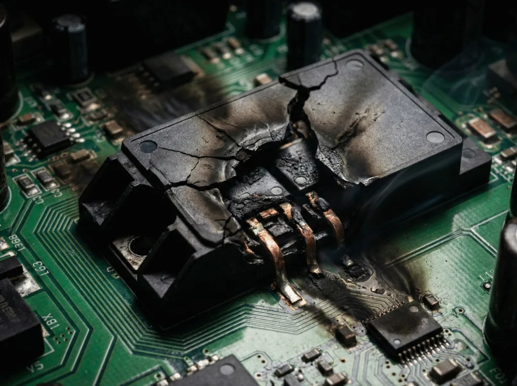
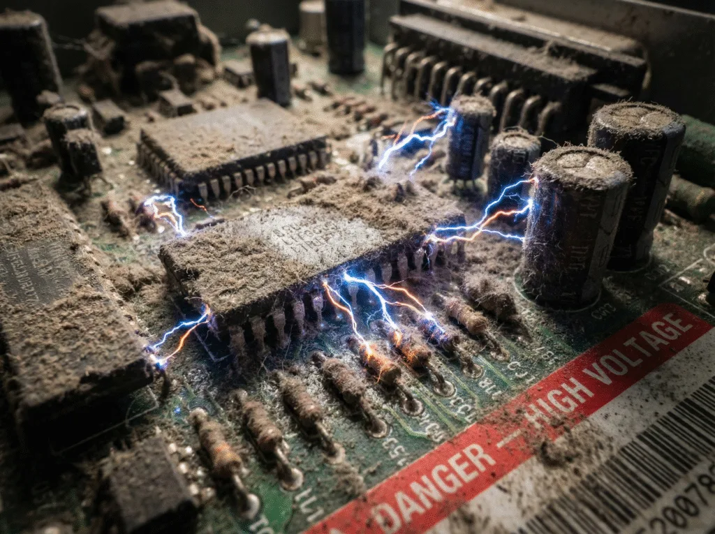
VFD interference is essentially high-frequency noise generated by the switching actions of power electronic devices—the IGBT modules in VFD drives switch on and off thousands of times per second (according to the VFD operating principle), leading to two types of pollution: conducted EMI from the VFD entering the power grid via cables, and radiated electrical noise from the VFD leaking from the VFD panel housing. The hazards directly cause PLC malfunctions, sensor signal distortion, and system downtime, and no industrial site is immune. This article will address three core challenges: How VFD Interference Affects Microcomputer Control Boards, How VFDs Resist External and Internal Electrical Interference, and How Poor Power Grid Quality Leads to VFD Malfunctions, providing a comprehensive solution from noise sources to propagation paths.
How VFD Interference Affects Microcomputer Control Boards
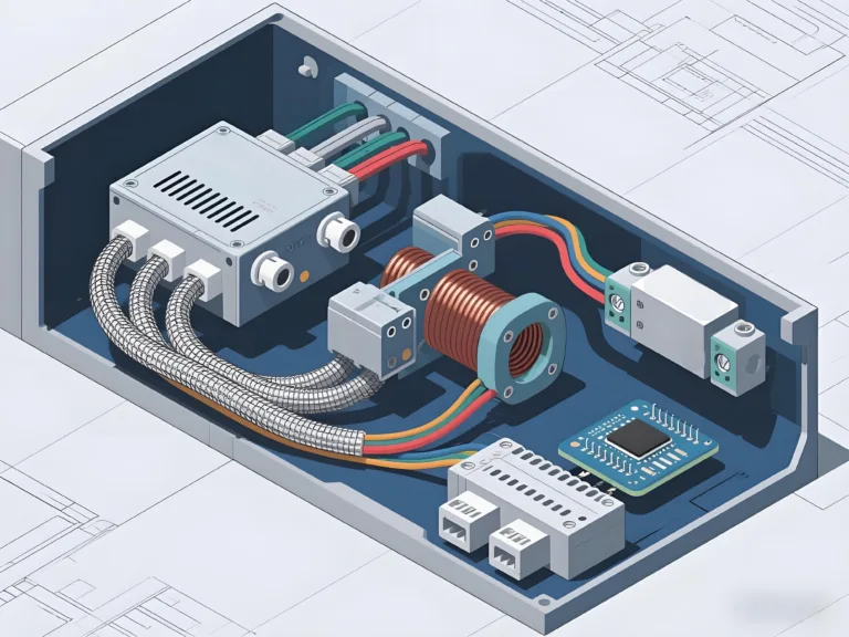
In control systems that use variable frequency drives (VFDs), microcomputers or PLCs are commonly employed. During system design or retrofit, special attention must be paid to vfd interference affecting the control boards. Because many custom-built microcomputer control boards have poor design practices and do not comply with international EMC standards, introducing a VFD often leads to vfd emi issues—both conducted and radiated—which can cause abnormal system behavior. Therefore, appropriate countermeasures are essential.
1.Proper Grounding
The grounding wires of motors and other power components must be reliably connected via a grounding busbar. The shield ground of the microcomputer control board should preferably be connected to an independent ground. In environments with severe vfd noise issues, it is recommended to connect the shielding layer of sensors and I/O interfaces to the control ground of the board.
2.Power Input Filtering
Installing an emi filter for vfd, common-mode inductors, or high-frequency ferrite rings on the power input of the control board is a cost-effective way to achieve vfd emi suppression. In areas with heavy radiated interference—such as near GSM or wireless base stations—metal mesh shielding enclosures can be added around the control board.
3.Input and Output Filtering for the VFD
Adding an emi filter for vfd at the VFD input can suppress conducted emissions into the power grid. Installing input AC and DC reactors (L1, L2) improves power factor and reduces harmonic pollution. In cases where the motor is located over 100 meters from the VFD, an output AC reactor (L3) is recommended to address leakage currents caused by the distributed parameters between output cables and ground, and to minimize external radiated emissions. A highly effective method is using steel conduit or vfd shielded cable, with the conduit shell or cable shield reliably grounded. However, if an output reactor (L3) is not installed, using steel conduit or vfd shielded cable can increase distributed capacitance to ground and may lead to overcurrent faults. In practice, one or several of these methods are typically selected based on system needs.
4.Shielding and Isolating Analog Signals
Analog sensor inputs and control signals should be properly shielded and electrically isolated. It is recommended to avoid using analog signals in VFD systems, especially when the control distance exceeds 1 meter or crosses multiple cabinets. VFDs usually support multi-speed settings and digital frequency control, which are sufficient for most use cases. If analog control is necessary, be sure to use vfd shielded cable and apply single-point grounding at either the sensor or VFD side. If vfd interference persists, DC/DC isolation is required. This can be achieved using standard DC/DC modules or by converting the analog signal to frequency via V/F conversion, then isolating through optocouplers and feeding the signal into the frequency input terminal.
How VFDs Resist External and Internal Electrical Interference
When high-frequency impulse loads such as welding machines, electroplating power supplies, or electrolytic power supplies are located near the VFD’s power supply system—or when slip-ring motors are used—vfd interference can easily cause the VFD to trigger protection faults. To reduce the impact of vfd emi, the following measures are recommended:
1.Add Filtering Components at the Input Side
Install inductors and capacitors at the input side of the VFD to form an LC filter network. This forms a basic vfd rfi filter setup that helps shield the VFD from external high-frequency noise.
2.Isolate the VFD Power Supply
Ensure the VFD receives power directly from the transformer’s low-voltage side. This practice enhances the reliability of vfd installation and avoids shared lines with noise-generating loads.
3.Use a Dedicated Transformer When Possible
If conditions allow, use a separate transformer exclusively for the VFD. This helps isolate vfd interference at the power source level.
4.Shield External Control Wiring
When using external digital control terminals for switching signals, and the vfd control wiring is long, shielded cables should always be used. If both control and power lines are laid in the same cable trench, the control lines must be shielded, and the main power lines should be routed through steel conduit to minimize mutual interference and prevent VFD malfunctions due to vfd interference.
5.Suppress Analog Input Interference
When analog control terminals are used, if the wiring distance is less than 1 meter, shielded cables with single-point grounding at the VFD side are sufficient. In longer or high-noise environments, where vfd analog input interference is likely, add DC/DC isolation modules on the VFD side, or use a V/F converter to provide frequency input commands instead of analog voltage/current control.
6.Improve Communication Reliability
For external communication terminals, use shielded twisted-pair cables and connect the VFD-side shielding layer to PE. If vfd interference remains severe, grounding the shield at the control power supply ground (GND) is also an option.
For RS232 communications, keep the control line under 15 meters. If longer distances are needed, reduce the baud rate; for example, communication at 100 meters typically requires speeds below 600 bps.
For RS485 communication, terminal matching resistors must be considered. In digital control vfd systems using high-speed fieldbus communication, use specialized communication cables and multi-point grounding to ensure higher reliability and better EMI immunity.
How Poor Power Grid Quality Leads to VFD Malfunctions
In industrial settings where high-frequency impulse loads such as welding machines, electroplating power supplies, or electrolytic power units are present, voltage fluctuations and flicker are common, leading to serious vfd power grid issues. When hundreds of VFDs and other capacitive rectifying loads operate simultaneously in a workshop, the system experiences severe vfd harmonics, significantly polluting power quality and causing substantial equipment-level vfd interference. In mild cases, systems fail to operate continuously; in severe cases, the input circuit of equipment may be damaged.
To mitigate vfd interference, the following measures are recommended:
1.Add Static Reactive Compensation Devices
In environments with high-frequency impulse loads, users are advised to install reactive power compensation equipment, such as vfd pfc systems, to improve the power factor and enhance power quality vfd performance.
2.Use Centralized Rectification and DC Bus Sharing
For workshops with a high concentration of VFDs, centralized rectification and a shared DC bus supply are recommended. A 12-pulse rectifier configuration is preferred, as it significantly reduces vfd harmonics, saves energy, and is especially suited for applications with frequent braking, motoring, and regeneration. This approach helps suppress vfd interference during dynamic load transitions.
3.Install Passive Harmonic Filters
Adding a passive harmonic filter (LC filter) at the input side of the VFD is a cost-effective, reliable solution to suppress input harmonics and improve the power factor. It is particularly effective in reducing vfd power grid issues and limiting vfd interference at the supply level.
4.Use Active PFC Devices
For applications requiring superior power quality, users may install active vfd pfc equipment at the VFD input. Although more expensive, this solution offers the best performance in eliminating vfd interference and ensuring high system stability—ideal for scenarios with stringent power quality vfd requirements.
Conclusion – Building EMI-Resilient VFD Systems
In complex electromagnetic environments, building EMI-resilient VFD systems is essential. Installing a passive harmonic filter and VFD line reactor on the input side effectively suppresses VFD harmonics and enhances grid stability. Implementing VFD PFC devices further improves the power factor and minimizes harmonic interference at the source. Proper grounding, analog signal isolation, and shielding techniques help reduce VFD interference risks. For high-frequency impact loads or centralized power setups, addressing VFD power grid issues systematically ensures stable and efficient equipment operation.

