7 Ways to Solve VFD Interference Causing Relay Issues
Introduction
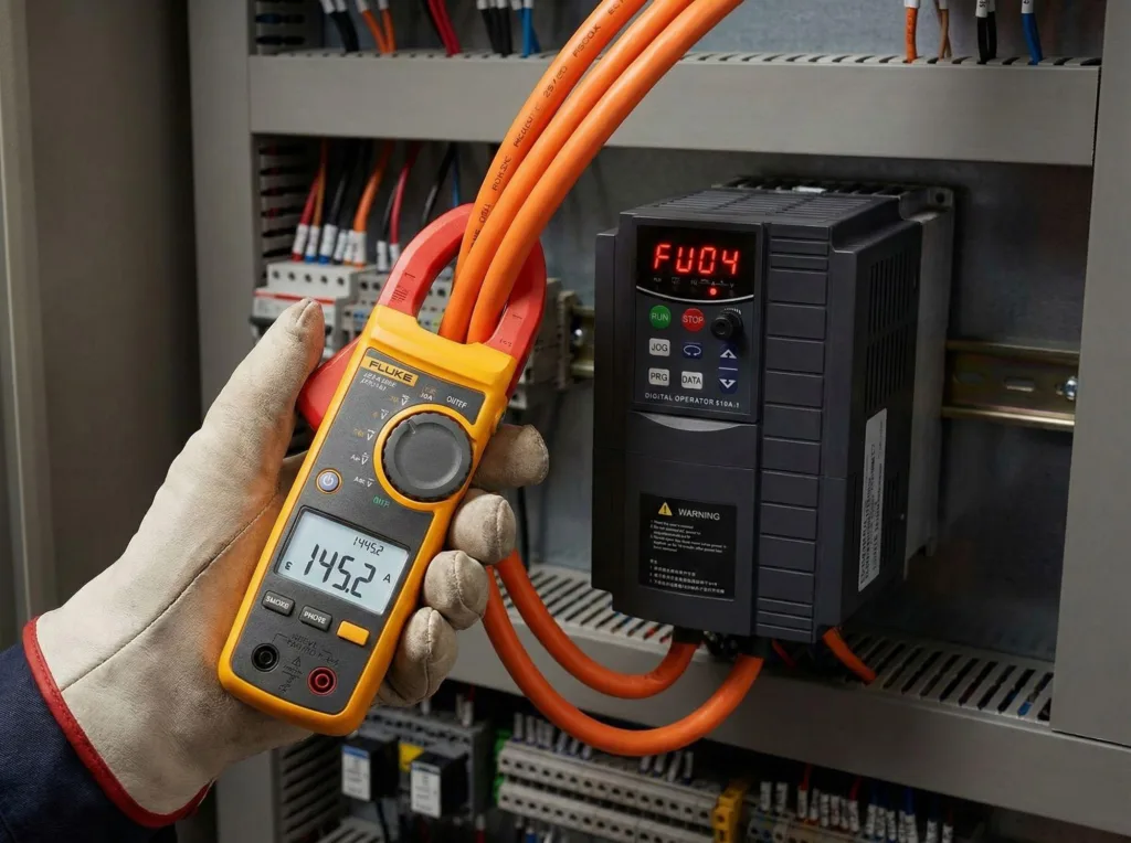
Today, I’d like to share a real-world VFD interference case I encountered on-site: a 200kW variable frequency drive (VFD) was causing a relay to malfunction during operation due to electromagnetic interference (EMI). So, how do we solve this?
Before diving into the technical response, let me stress one key point: VFD interference issues on-site are highly complex and can rarely be eliminated by a single measure. They are systemic by nature, often caused by a combination of factors — ranging from civil construction layout, equipment positioning, cable routing, separation of power and signal lines, grounding design, to VFD hardware quality and control loop wiring.
Once VFD EMI problems arise, they can be extremely difficult to diagnose and resolve without experienced hands. Having spent decades in the field, I’ve dealt with countless similar issues — and many large and mid-sized companies often call me for support. With this case, I’d like to walk you through my practical approach and field-tested techniques, hoping it offers clarity and real solutions to those facing similar challenges.
1.The VFD Itself Is a Source of VFD Interference
This is beyond dispute.
- On the input side: The VFD’s rectifier bridge only conducts during part of the AC sine wave, injecting large amounts of 5th and 7th harmonic distortion, along with switching noise, back into the power grid — degrading power quality.
- On the output side: The IGBT module inside the VFD operates as a high-speed switch, generating high-frequency harmonics (2kHz, 4kHz, 6kHz, up to 16kHz) with each switching event. These disturbances propagate along the output path and into connected systems, becoming a significant cause of VFD interference.
That’s why once a VFD is online, unexpected VFD-induced EMI often crops up in ways non-specialists can hardly anticipate.
2.Seven Practical Measures to Suppress VFD Interference (From Simple to Complex)
2.1.Shielded Cable Grounding — Always Ground the Shield Layer
The most fundamental and effective countermeasure is to properly ground the shielded cable between the VFD panel, the drive, and the motor.
This is often overlooked, but poor shielding or grounding is one of the most common root causes of persistent VFD EMI in industrial systems.
2.2.Ground the Relay Cabinet Separately; Tie 24V Negative to Earth
Ensure that the relay cabinet chassis is solidly grounded. In addition, tie the negative side of the 24V control power supply to ground. This setup allows any induced high-frequency noise or harmonics to safely discharge, reducing relay interference and false triggering caused by VFD interference.
2.3.Isolate Power and Control Grounding Systems
VFD Drives and motors operate in the high-power domain and generate high-frequency electrical noise. PLCs and relay circuits operate in the low-power domain and are sensitive to these disturbances.
Never allow control and power systems to share the same ground. Establish a separate protective ground for control circuits, isolating them from high-frequency feedback paths that worsen VFD interference and facilitating faster fault diagnostics.
2.4.Separate Power and Signal Cable Routing; Maintain Minimum 40 cm Distance
Power cables (VFD output, motor leads) and control cables (PLC I/O, sensors) must be routed separately. All control lines should be shielded.
- Japan’s standard: ≥10 cm
- Europe’s standard: ≥22 cm
- My recommendation: ≥40 cm for added safety
This separation minimizes radiation coupling and EMI issues, reducing the impact of VFD interference on relay logic and sensor accuracy.
2.5.RC Snubber Circuits Across Relay Coils
Install an RC snubber across each relay coil terminal. This suppresses harmful voltage spikes and high-frequency harmonics at their source — a powerful method to eliminate relay chatter or false operation due to VFD EMI.
2.6.Reduce Carrier Frequency — But Only If the Motor Stays Stable
Lowering the PWM carrier frequency of the VFD reduces output harmonics, helping contain electromagnetic interference. But this comes with a caveat: the motor must remain vibration-free.
Gradually decrease the carrier frequency while monitoring the motor. If vibration or noise emerges, immediately revert to the previous stable value. Further reduction may cause mechanical or operational issues — and may not effectively control VFD interference.
2.7.Add Line Reactors to Input and Output
- Input reactor: Filters incoming grid noise and voltage distortion, stabilizes DC bus voltage
- Output reactor: Dampens high-frequency switching noise from IGBT modules, protecting motor windings and reducing VFD interference propagation
These components are critical for high-power installations, improving electromagnetic compatibility (EMC) and overall system resilience against VFD-induced EMI.
Conclusion
This case highlights the full scope of diagnosing and mitigating VFD-induced EMI issues. As you can see, VFD interference is not a software bug nor a faulty relay — it’s a complex system-level challenge involving electrical design, grounding, wiring architecture, and parameter tuning.
Only by conducting comprehensive system-wide diagnostics can we fully resolve EMI issues caused by VFDs. I hope this guide proves useful in your own projects. If you’re an electrical technician or maintenance engineer, make these principles part of your toolkit — they can help you avoid costly downtime and ensure long-term system reliability.