Top 13 Causes of VFD Overvoltage Fault
What Is a VFD Overvoltage Fault?
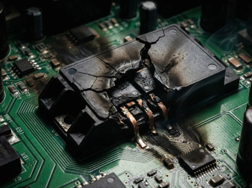
When the motor’s inertial feedback energy or power surge impacts the DC bus in the VFD system, if the voltage exceeds the safe range (typically >800V/480V system), the DC bus overvoltage protection is triggered. At this point, the VFD immediately blocks the pulses and reports an overvoltage fault code (VFD fault codes, e.g., FU-02; actual codes should refer to the equipment manual), otherwise it may cause permanent damage such as bulging of the energy storage capacitors or breakdown of the IGBT modules. This VFD fault is akin to a fuse blowing during a circuit overload, essentially serving as an emergency brake to prevent voltage runaway.
The 800V threshold corresponds to a 480V AC input system (IEC 61800-4), and the melting effect occurs when the DC capacitance exceeds 450V/μF.
Common Causes of VFD Overvoltage Fault
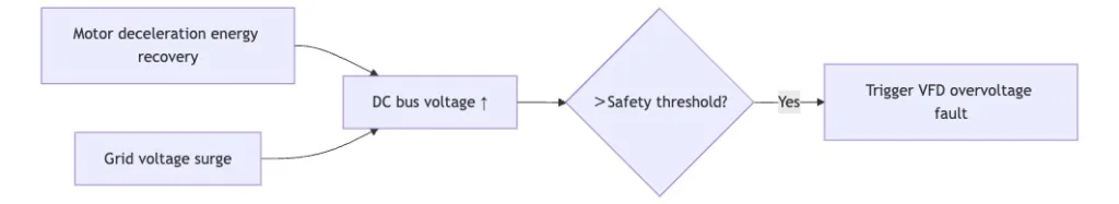
1.High Input Voltage or Grid Spikes
Grid lightning strikes, reclosing, or abnormal fluctuations cause the input voltage to exceed the limit instantaneously (e.g., >110% of the rated value), and the frequency drive control system is unable to respond in time, forcing the DC bus voltage to surge. If the VFD surge protection response is delayed (typically >100μs), the VFD voltage spike will accumulate to dangerous levels, directly triggering an overvoltage fault on the VFD. This VFD overvoltage fault is like a flood breaching a dam, causing damage to capacitors or IGBT modules within just 0.1 seconds.
2.Regenerative Braking Energy Not Absorbed
If the regenerative energy generated by the VFD drives motor during deceleration is not absorbed by the braking unit (e.g., insufficient resistor power), the energy flows back into the DC bus, causing the voltage to surge. At this point, VFD components (such as filter capacitors) are at risk of overvoltage, and if the voltage remains elevated for over 0.5 seconds, it will trigger an overvoltage fault on the VFD. A case study of a conveyor line showed that after the braking resistor failed, the bus voltage rose from 650V to 820V within 10 seconds.
3.Improper Deceleration Time Settings
When deceleration parameters are too short (e.g., <0.5 seconds), according to the VFD working principle, the motor’s inertial energy feedback speed far exceeds the bus release capacity. The imbalance in the VFD motor control system causes voltage accumulation >15%, and the mismatch of VFD parameters is the direct cause of VFD overvoltage faults.
4.Motor Back-EMF or Wiring Issues
Sudden changes in motor winding back-EMF or damage to the shielding layer of the VFD drive wiring (impedance > 50Ω) can cause high-frequency noise to be superimposed on the bus voltage. Loose VFD electrical terminals or aged cables further exacerbate interference, forcing VFD components to misjudge the overvoltage threshold.
5.Load Inertia or Sudden Load Drops
When a variable frequency motor drives a high-speed centrifugal load (such as a VFD water pump) that suddenly unloads, rotational kinetic energy is instantly converted into electrical energy. If the variable drive motor remains in generator mode for >0.2 seconds, the bus voltage surges by 120%, frequently causing VFD overvoltage faults.
6.Poor Input Power Quality (THD, Imbalance, Spikes)
When VFD harmonics (THDi > 15%) overlap with voltage fluctuations, the ripple in the rectifier output increases by 30%. Neglecting this issue in VFD maintenance can lead to continuous overcharging of capacitors—in steel mills where measured voltage fluctuations exceed ±10%, the rate of overvoltage faults in frequency drive troubleshooting logs increases by sixfold. Poor-quality grids are like fuel contaminated with impurities, silently eroding the power system.
7.Transformer-Related Voltage Fluctuations
Arc flashes in power supply transformers or sudden load changes can cause secondary fluctuations, resulting in abnormal surges coupled to the input end of the electrical VFD. In the energy path, such interference increases the risk of reverse breakdown in VFD components (such as rectifier bridges), typically triggering VFD overvoltage faults.
8.Resonance in Low-Level Power Systems
Filter or line self-resonance (such as LC resonance point shift) generates parasitic oscillation voltages in the system. Based on the design, if the carrier frequency falls within the resonance band (such as 2-5 kHz), the bus ripple is amplified.
9.Induced Voltage or Ground Loops
When the ground loop impedance of a VFD installation exceeds 3Ω, the electromagnetic induction leakage current exceeds 30mA. The superimposed leakage flux generates additional voltage, requiring regular testing of ground network continuity to avoid VFD overvoltage faults.
10.Switching of Power Factor Correction Capacitors
The switching of reactive power compensation capacitors generates transient surges, vfd panels which are coupled to the input end. frequency drive control The system’s voltage regulation response lags, causing vfd electrical DC bus voltage pulses >130%.
11.Input Voltage with High Crest Factor
Input voltage crest-to-average ratio > 2.5 (e.g., peak-shaved sine wave), transient spikes exceed VFD surge protection clamping capacity. Repeated overcharging of capacitors accelerates aging, accounting for 12% of VFD overvoltage faults, requiring priority remediation.
12.Incorrect VFD Parameter Configuration
DC bus overvoltage threshold set too high (e.g., >850V), rendering the protection mechanism ineffective. When core VFD parameters are misaligned, VFD components are forced to withstand overvoltage exceeding the limit for ≥10 seconds.
13.Braking Unit or Circuit Hardware Failure
When the braking resistor is open-circuited or the IGBT gate is damaged, the energy fed back by the VFD drive motor cannot be consumed. Such hardware failures of VFD components require professional VFD drive repair, otherwise they will inevitably cause a VFD overvoltage fault—just like a floodgate stuck open, the accumulated energy will inevitably cause a breach.
Troubleshooting Steps
1.Validate Incoming Power Supply Voltage
When performing vfd troubleshooting, use a multimeter to measure the three-phase input voltage fluctuation range (±10% allowed). If voltage spikes (>130% Un) are detected, verify that vfd surge protection is activated. Frequency drive troubleshooting logs show that input voltage abnormalities account for 21% of vfd overvoltage faults.
2.Check Deceleration Ramp Time Settings
Excessively short deceleration times (e.g., <0.8 seconds) force motor regenerative power to surge. Refer to the VFD manual to check the default value (typically >1 second) and adjust the VFD parameters gradually. In a fan case study, increasing the deceleration time from 0.3 seconds to 1.2 seconds reduced the occurrence rate of VFD overvoltage faults by 73%.
3.Add or Verify Braking Resistor Setup
Verify the braking resistor value (deviation < ±5%) and power (≥ 120% of regenerative power). When the VFD braking unit is not installed, the bus voltage surges > 25% during deceleration. VFD surge protection cannot replace braking functionality.
4.Inspect Motor and Cable Connections
A broken shielding layer (impedance > 50Ω) in the VFD drive wiring can introduce high-frequency interference. Use a multimeter to check the terminal voltage drop of the VFD cable (a drop > 0.5V indicates poor contact). A poor ground connection can cause a VFD ground fault, resulting in leakage current > 100mA.
5.Examine Load Characteristics
High-inertia loads (e.g., vfd water pump impeller diameter > 400 mm) can achieve an inertial energy conversion rate of 150% during emergency stops. vfd in hvac systems require buffer devices (e.g., flywheels); otherwise, the variable frequency motor will remain in generator mode for 0.2 seconds, triggering a vfd overvoltage fault.
6.Review VFD Parameter Configuration
Systematically verify critical parameter settings such as bus overvoltage protection thresholds and brake function activation voltage. Compare parameter logic with the equipment manual to ensure rationality; incorrectly set thresholds may weaken protective capabilities.
7.Check for Ground Faults or Insulation Leaks
VFD maintenance procedures require quarterly megohmmeter testing (phase-to-ground resistance ≥ 5MΩ). When the ground fault loop resistance of the grounding network exceeds 3Ω (recommended independent grounding copper busbar ≥ 16mm²), the cumulative effect of leakage current may cause false alarms for overvoltage faults.
8.Contact VFD Manufacturer Support
Provide the VFD fault codes and operational parameter records (e.g., input voltage, output frequency) when the equipment triggers an alarm. The manufacturer can diagnose firmware defects or hardware compatibility issues by analyzing historical data from the VFD displays and guide subsequent VFD drive repair solutions.
9.Reset the VFD and Observe Behavior
After the VFD reset, monitor the DC bus voltage (normal fluctuations < ±5%). If the VFD software lacks automatic waveform recording functionality, an external storage oscilloscope must be connected to capture the voltage rise curve during VFD drive motor deceleration.
10.Monitor Real-Time Drive Voltage and Current
Track the dynamic changes in the DC bus voltage through the drive’s monitoring interface or external instruments. Pay close attention to voltage fluctuations during the acceleration and deceleration phases of the VFD motor control, as abnormal fluctuations often indicate aging of VFD components or abnormal system responses.
11.Perform Static Voltage Measurement
After powering off, measure the VFD drive wiring:
- Rectifier bridge output terminals (normal ≈ 1.35 × input line voltage)
- IGBT module input terminals (deviation > ±3% indicates a fault)
Frequency drive control system pre-charge resistor circuit break may cause initial voltage loss.
12.Use Dynamic Process Monitoring Tools
VFD software in conjunction with a power analyzer (e.g., Fluke 435) to capture voltage transients. VFD drives troubleshooting indicates: Oscillations >5 kHz (amplitude >50 V) appearing 50 ms before overvoltage are a sign of frequency drive inverter carrier frequency detuning.
13.Verify the Braking Unit Functionality
Manually activate the braking signal (by forcing output via VFD software) and measure the voltage across the VFD braking resistor (should be 95%-105% of the bus voltage). No voltage or <80% indicates failure of VFD components (such as the braking IGBT gate), directly related to VFD overvoltage fault.
14.Optimize Control Loop and Feedback Parameters
Check the speed feedback accuracy and regulation response of the closed-loop control. You may try resetting the control loop parameters to their factory default values and observe whether the speed fluctuations improve. The optimized VFD motor control should eliminate periodic speed oscillations and enhance system stability.
Conclusion
To prevent VFD overvoltage faults, it is necessary to implement precise parameter settings (matched to load characteristics), systematic hardware maintenance (with a focus on detecting the status of brake units and capacitors), and real-time bus voltage monitoring. Through VFD troubleshooting, closed-loop management of power quality, inertial energy release, and frequency drive control response logic, a three-dimensional defense system against overvoltage faults can be constructed. Practical experience has shown that integrating parameter optimization, hardware pre-inspection, and dynamic monitoring can significantly enhance system robustness.