RS-485 Problems in VFD Systems: 3 Causes & 4 Solutions
Today, we will discuss the three main causes and four solutions for RS-485 communication abnormalities caused by variable frequency drive (VFD) operation.
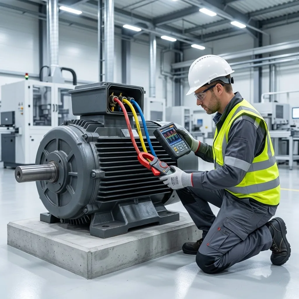
Recently, a customer reported that whenever their VFD starts running, the RS-485 communication is interrupted, and a voltage tester shows a light when tested inside the VFD control cabinet.
This is a 90kW(121HP) VFD driving a 70kW motor. Reactors are installed on both the input and output sides of the VFD. However, every time the VFD is started, the RS-485 communication is interrupted, and the voltage tester in the control cabinet lights up.
Preliminary Analysis of the Issue
Once the VFD starts, the RS-485 communication immediately interrupts, further indicating:
There is a high induced electromotive force on the control cabinet, forming a strong electric field inside the cabinet. As long as the strong electric field exists, the voltage tester will light up.
VFD Interference Analysis
Although reactors are installed on both the input and output sides of the VFD:
- Input reactors prevent the VFD from interfering with the power grid
- Output reactors suppress harmonic propagation in the motor power cables and also mitigate voltage spikes
However, these only suppress interference on the lines. If the VFD itself or the control cabinet is not grounded or has poor grounding, strong induced voltages will still exist.
Proper Grounding is Critical
Simply ensure that the VFD housing and control cabinet are properly grounded.
- After grounding, the potential of the VFD housing is zero
- The potential of the control cabinet housing is also zero
- When tested with a voltage tester, it no longer lights up, indicating no induced electric field inside, and interference is significantly reduced
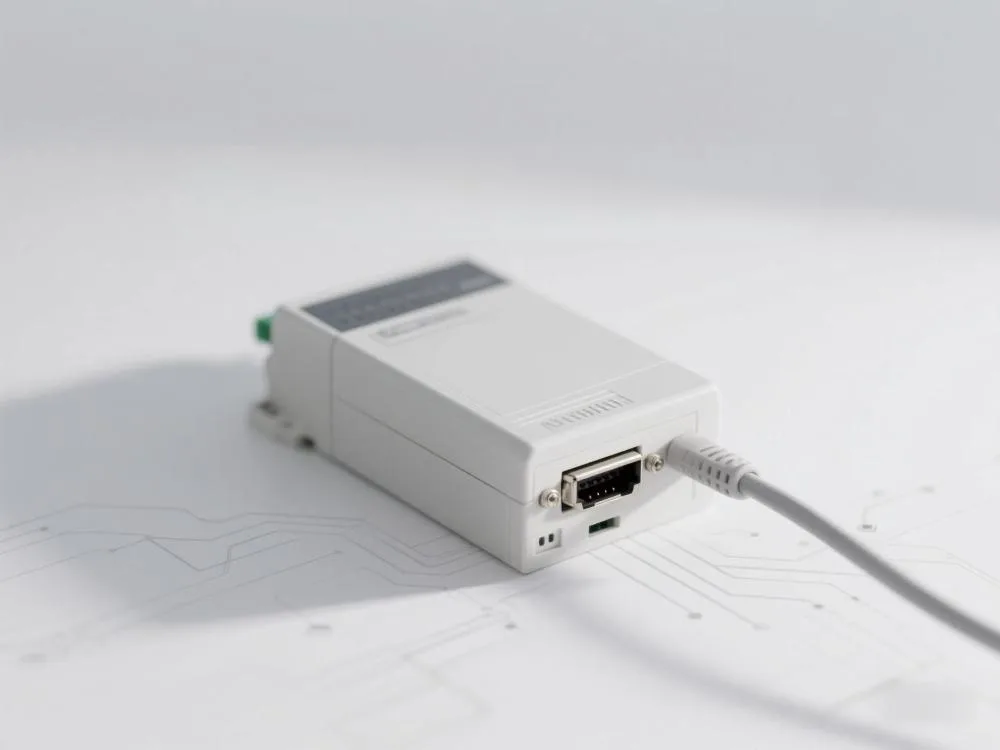
RS-485 Communication Specifications
- Shielded cables must be used. If shielded cables are not used, the RS-485 output signal may change from a standard differential signal to a rectangular wave, causing significant harmonic interference
- The shielding layer must be properly grounded. This effectively suppresses electromagnetic interference or induced electromotive force from surrounding equipment
- If RS-485 communication needs to be transmitted over long distances with power cables: Even with shielded cables, interference cannot be completely eliminated. In such cases, it is recommended to use an optical converter to convert the RS-485 signal into an optical signal for transmission, then convert it back, thereby fundamentally resolving the interference issue
Another common cause — incorrect parameter settings
If the communication parameters of the variable frequency drive are set incorrectly, it may also cause RS-485 communication abnormalities.
The three main causes of RS-485 communication abnormalities caused by inverter operation
1.Signal interference
If the RS-485 communication module is not grounded, it can cause charge accumulation, enhance interference, and potentially lead to communication interruptions
Solution:
Connect the shielding wire of the RS-485 communication cable to the grounding terminal of the inverter to achieve single-ended grounding, effectively reducing interference.
2.Wiring errors
Hardware wiring errors are also common causes
Ensure that the PE terminal of each variable frequency drive is grounded at a single point nearby, and interconnect the grounding wires. RS-485 communication cables should use shielded cables and adopt a single-ended grounding method.
If the issue persists, try using an RS-485 module with isolation functionality.
3.Incorrect parameter settings
Inconsistent communication parameters (baud rate, data bits, stop bits, parity bits, etc.) will result in communication failure.
Ensure that the parameters of the variable frequency drive and the host computer are consistent; if the issue persists, try upgrading the firmware or using other debugging tools for troubleshooting.
Four preventive measures
- Use shielded cables to reduce environmental electromagnetic interference.
- Ensure proper grounding to prevent signal interference caused by charge accumulation.
- Regularly inspect communication lines to prevent aging, poor contact, and other potential issues.
- Properly configure communication parameters to ensure consistency with communication protocols of other devices.
Typical Application Scenarios
Scene | Recommended Solution |
|---|---|
High-Interference Workshops | Optical fiber conversion + fully shielded cabling + independent grounding (ground resistance ≤ 2Ω) |
Multi-Device Networking | Isolated RS-485 module (e.g., BH-485G) + optimized bus topology |
Legacy System Upgrades | Install magnetic ring filters (wrap power cable 3–4 turns) + isolated power transformer |