Top 8 Disadvantages of VFD
Introduction — Understanding the Limitations of VFDs
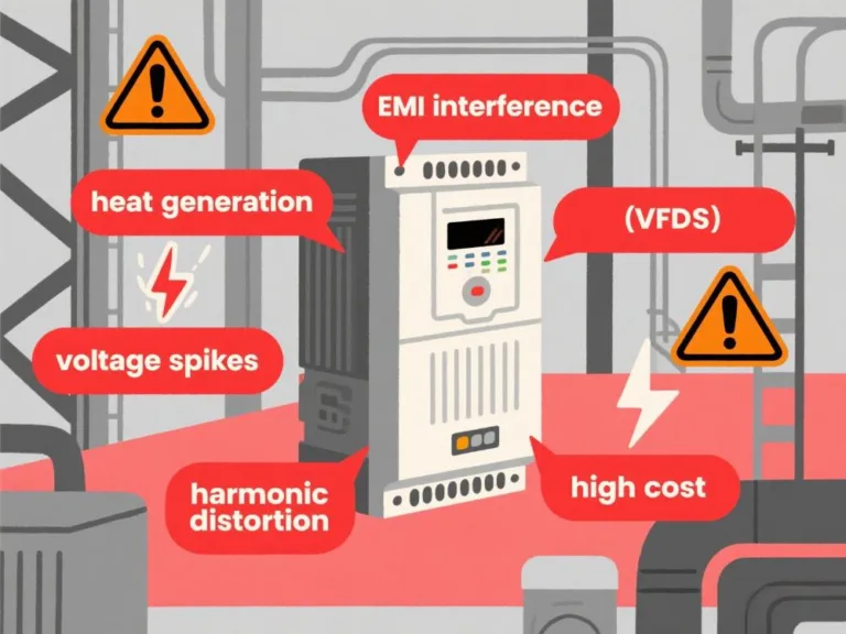
Variable frequency drives (VFDs) reshape motor energy flow through high-speed semiconductor switching (core VFD working principle), creating energy-saving value in HVAC and pump systems. However, their electrical characteristics harbor contradictions: grid harmonics (THDi > 30%), high-frequency radiation, and a 15-25% initial premium. When deploying VFD drives, it is essential to clearly understand these disadvantages of VFDs—the flip side of the energy efficiency revolution involves delicate trade-offs between electromagnetic compatibility costs and system compatibility.
Disadvantages of VFD – What You Need to Consider
1.High Initial Costs
VFD drives require additional investment in dedicated cables (steel-lined shielded type with a 150% premium), harmonic filters (12% of system cost), and customized commissioning labor, resulting in variable frequency drive costs that are 25% higher than direct starting. However, energy savings typically pay for themselves within three years.
2.Complexity in Installation and Configuration
VFD working principle requires precise configuration of key items such as voltage/frequency curves, carrier frequency (2-15kHz), PID parameters, and motor protection thresholds. During implementation, EMC wiring specifications (power/control cables separated by >200mm) and safety interlock logic must be addressed. The operational complexity of VFD basics extends the average on-site commissioning time by 3–5 days, significantly longer than traditional starting systems.
3.Harmonic Distortion and Power Quality Issues
VFD harmonics inject 5th, 7th, and 11th harmonics (THDi > 30%) into the power grid, causing transformer overheating and capacitor cabinet resonance. Mitigation requires adding a 12% input reactor (mandatory) or an active filter with a cost ratio of 25%, and dedicated VFD cables only alleviate 30% of local radiation interference. These core disadvantages of VFDs result in a 15% increase in overall system investment, and voltage distortion further threatens the operation of precision equipment.
4.Electromagnetic Interference (EMI/RFI)
VFD EMI originates from IGBT switching tens of thousands of times per second (dv/dt > 5000 V/μs), interfering with sensor/PLC signals. Mandatory installation of a VFD RFI filter (costing 8% of the system) and fully shielded cables (coverage ≥ 95%) is required for compliance.
5. Heat Generation and Cooling Requirements
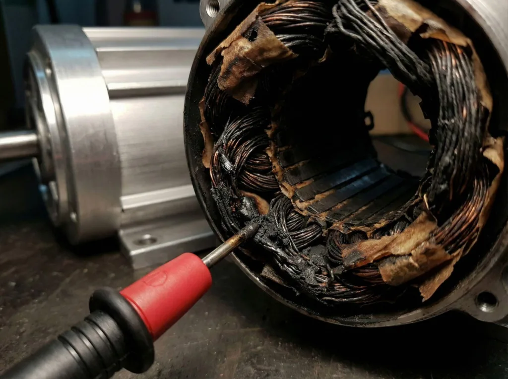
During operation, approximately 3% of the power of an AC motor VFD is converted into heat energy (IGBT switching losses + wire resistance), causing the winding temperature of VFD motors to rise to ≥50°C. A forced cooling system (air cooling/air conditioning) must be installed for the VFD panel, increasing the equipment volume by 15% and energy consumption costs by 10%. In high-temperature environments, additional derating is required for operation.
6. Sensitivity to Harsh Environments
The precision VFD electrical components (such as electrolytic capacitors/IGBTs) in variable frequency drives experience a 300% increase in insulation aging rate in environments where the temperature exceeds 40°C, humidity exceeds 85%, or dust concentration exceeds 5 mg/m³, resulting in a significant reduction in capacitor lifespan to 2 years (compared to the normal lifespan of over 10 years). Mandatory upgrades to IP54/IP65-rated enclosures (cost increase of 25%) and anti-condensation heaters (power consumption increase of 3%) are required. In salt fog/corrosive environments, stainless steel enclosures are also necessary (additional cost increase of 15%), significantly increasing deployment costs and operational maintenance intensity.
7. Dependence on Regular Maintenance and Quality
VFD maintenance requires replacing electrolytic capacitors every two years (lifespan < 8 years) and cleaning cooling fans (dust accumulation > 3 mm reduces efficiency by 40%). Poor-quality variable frequency drive brands have a relay contact erosion rate as high as 30% per year. These disadvantages of VFDs result in average annual maintenance costs exceeding 3% of the equipment price, which is much higher than traditional starters.
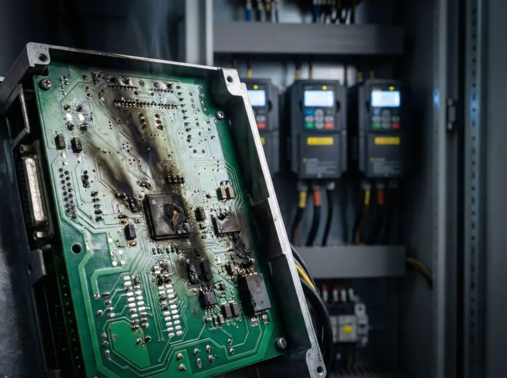
8. Voltage Transients and Overvoltage Risk
Grid flicker or lightning strikes can cause >6kV VFD voltage spikes (3μs pulse width), burning out IGBT modules and capacitors. Mandatory configuration of VFD surge protection (8/20 μs waveform discharge > 40 kA) and installation of dedicated VFD cable (shielding layer grounded at both ends) are required; otherwise, the failure rate will increase by 300%. Low-quality surge protectors only absorb 20% of the energy.
When Should You Use a Variable Frequency Drive?
1.High-efficiency application scenarios
- VFD in chiller (refrigeration unit):
- Frozen water load fluctuations > 30% (more than 8 starts/stops per day)
- Cooling tower fan > 30 kW (low-frequency energy savings > 40% at 35 Hz)
- Applicable parameters: Variable water temperature control with △T ≥ 5°C
- VFD pumps (pump systems):
- Variable flow conditions (speed ratio ≥ 1:3)
- Pipeline pressure fluctuation tolerance < ±0.2 MPa
- Typical benefits: 45 kW centrifugal pump saves 126,000 kWh annually
- VFD compressor (compressor):
- Multi-unit control (≥3 units in parallel, pressure band switching > 6 times/hour)
- Unloading operation time > 25% of total cycle
- AC variable frequency drive (high-precision drive):
- Extruder screw speed fluctuation < ±0.15%
- Textile winding tension control error ≤ 1.5%
2.Caution/Disable Scenarios
Operating conditions | Technical limitations | Alternative solutions |
|---|---|---|
Constant speed equipment | Fire pumps/emergency power supply (annual operation < 20 hours) | Soft starter + mechanical valve |
Low-power equipment | < 0.75 kW (payback period > 10 years) | Capacitor speed control/pole-changing motor |
Harsh grid environment | Voltage fluctuations > ±15% (remote mining areas) | Wide voltage input VFD + voltage regulator |
High-risk explosion-proof areas | Non-ATEX/IS certified enclosures | Pneumatic drive/explosion-proof motors |
High-frequency start-stop loads | Rolling mills > 60 cycles/hour (IGBT overheating) | Hydraulic coupling + permanent magnet motor |
3.Operational Economic Boundary
- Investment Return Formula: ROI (annual) = [Annual Energy Savings × Electricity Price – Maintenance Costs] ÷ Equipment Purchase Cost
- Decision Threshold: When the load factor difference (△) is ≥35% and annual operating hours exceed 4,000 hours, the comprehensive benefits of a Variable Frequency Drive (VFD) exceed those of a traditional drive.
Note: Speed ratio = Qmax/Qmin, pressure tolerance refers to ANSI/B9.1 standards, explosion-proof certification includes ATEX/IECEx/UL 1203.
Conclusion — Is a VFD Always the Right Choice?
VFD is not a universal solution—its core limitations lie in VFD harmonics polluting the power grid (THDi > 30%), VFD EMI interfering with precision instruments, and reliance on VFD surge protection in complex environments. Three assessments must be conducted prior to implementation: 1) Load fluctuation rate ≥ 35% (otherwise energy savings will not cover VFD maintenance costs); 2) Grid stability (fluctuations < ±10%); 3) Installation environment cleanliness (dust < 5 mg/m³). In high-interference scenarios such as medical imaging or MCU production lines, even when deploying VFDs, dual shielded rooms (attenuation > 60 dB) are required. By acknowledging these disadvantages of VFDs, semiconductor speed control technology can evolve from an energy consumption trap into an energy efficiency engine.