Top Fixes for VFD Overvoltage and Resistor Burnout Issues
Field Case Study: Root Causes and Solutions for Repeated VFD Overvoltage and Braking Resistor Failure
Today, I’d like to share a classic yet challenging real-world case. It started with a comment from a mining industry user. While the issue seems straightforward at first glance, troubleshooting it is far from easy. This case is a textbook example of a VFD Overvoltage fault—something every engineer should be aware of.
Fault Background: Same VFD, Frequent Braking Resistor Burnouts
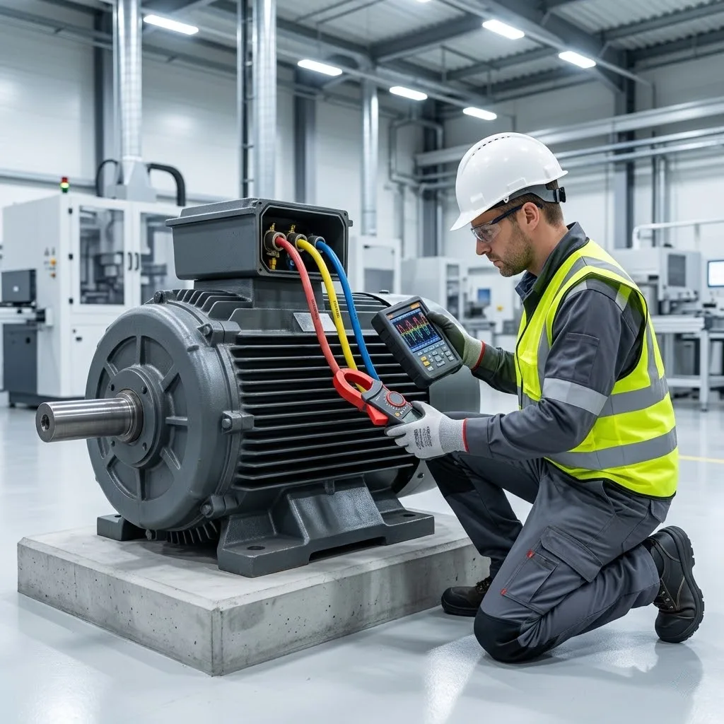
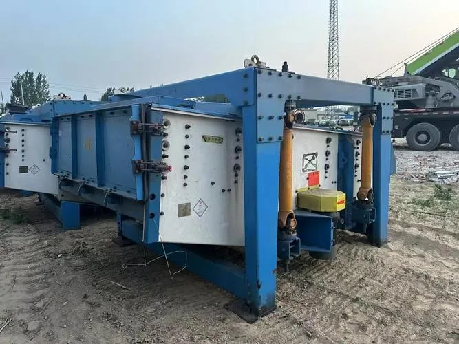
The equipment in question is a 10-meter-long reciprocating steel tray screener driven by a 7.5 kW, 6-pole three-phase asynchronous motor, controlled by an 18.5 kW VFD. The system has been operating stably for five years. During VFD installation, the user used 18-meter-long, 4 mm² copper-core cables. However, over the past two years, the VFD has been frequently burning out braking resistors.
Initially, a 1.5 kW braking resistor was used, which failed quickly. It was later replaced with a 4.8 kW, 36-ohm resistor, which offered slight improvement—but failed again within six months. The user asked us: Why is the braking resistor failing so often? Is it a vfd drive selection issue or a matter of incorrect control parameter settings?
Analysis of VFD Overvoltage Issues
1.Regenerative Energy Exceeds VFD Braking Capacity
At the heart of this issue is a VFD Overvoltage condition. Due to the massive structure and weight of the oscillating screen and its frequent reciprocating impact, the system generates extremely high mechanical inertia. During each reversal, the motor begins to regenerate—feeding energy back into the system (i.e., regenerative braking).
This regenerative energy flows into the VFD’s DC bus, rapidly increasing its voltage. Based on calculations, the peak regenerative power reaches up to 15 kW, while the 4.8 kW braking resistor cannot dissipate such energy in time. As a result, the VFD dynamic braking system becomes saturated, triggering dc bus overvoltage VFD faults and burning out the resistor.
2.Unreasonable VFD Parameter Settings Lead to Delayed Response
Further inspection revealed that the VFD’s acceleration time was set too short (default: 10 seconds), and the braking delay too long—resulting in poor responsiveness from the VFD braking system, making it unable to consume energy in time, causing sustained DC bus voltage spikes.
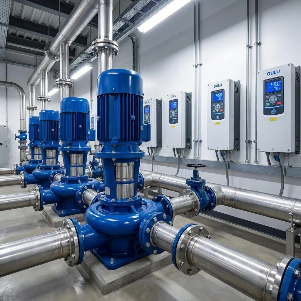
Additionally, the 4 mm² cable may be acceptable for standard vfd pump or vfd motor loads like water pumps, but it’s inadequate for high-inertia, vibration-heavy machinery. The thin cable increases line impedance and worsens voltage spike suppression—posing greater challenges for inverter DC bus protection.
Recommended Solutions
Long-Term Solutions (Highly Recommended)
- Recalculate VFD Braking Resistor Sizing The most direct and effective solution is to properly match the resistor to the actual load. A 10–15 kW corrugated resistor (~20 ohms) from a quality brand is recommended to improve overload tolerance.
- Upgrade to Regenerative VFD If budget permits, consider replacing the VFD with a regenerative VFD that features a bidirectional IGBT rectifier. Brands like Siemens and ABB offer these solutions. Instead of dissipating energy via resistors, the VFD sends the surplus power back to the grid—completely eliminating the VFD Overvoltage issue.
- Optimize Mechanical Damping Install hydraulic dampers or spring buffers at both ends of the screener. These absorb part of the kinetic energy during reversal, reducing the energy fed back into the VFD—a practical mechanical method to relieve VFD overvoltage conditions at the source.
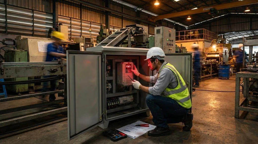
Temporary Solutions (For On-Site Engineers)
- Extend Acceleration Time to 20–30 Seconds Reduces system impact and limits sudden current spikes.
- Enable Braking Earlier (Set Brake Delay to 0.5 Seconds) Improves braking response speed and reduces the risk of triggering VFD Overvoltage alarms.
- Increase Overvoltage Threshold to 780V (Default: 760V) Gives the DC bus more headroom, enhancing system fault tolerance.
- Lower Carrier Frequency (e.g., from 4 kHz to 2 kHz) Reduces harmonic stacking and spike voltages, improving braking resistor lifespan.
- Replace with 6 mm² Cable to Improve Bus Impedance Matching Reduces voltage fluctuations and boosts system stability.
- Install Output Reactors Helps suppress high-frequency harmonics and electromagnetic interference—protecting both motor and vfd drives.
- Parallel Braking Resistors for Higher Power Capacity Two 4.8 kW resistors in parallel will double the power to 9.6 kW and reduce the resistance to 16 ohms, significantly improving energy absorption capacity.
Conclusion: VFD Overvoltage = Misjudged Regeneration Risk
This isn’t simply a matter of underpowered braking resistors. It’s a system-wide underestimation of the regenerative effects caused by high inertia. In such applications, traditional braking resistors are often insufficient. Only precise vfd braking resistor sizing or an upgrade to regenerative VFD technology can fully resolve the issue.
For engineers, understanding VFD Overvoltage goes beyond interpreting fault codes. It requires a full grasp of dynamic energy feedback and system-level design. We hope this case provides a clearer approach and more confidence when dealing with similar on-site faults.