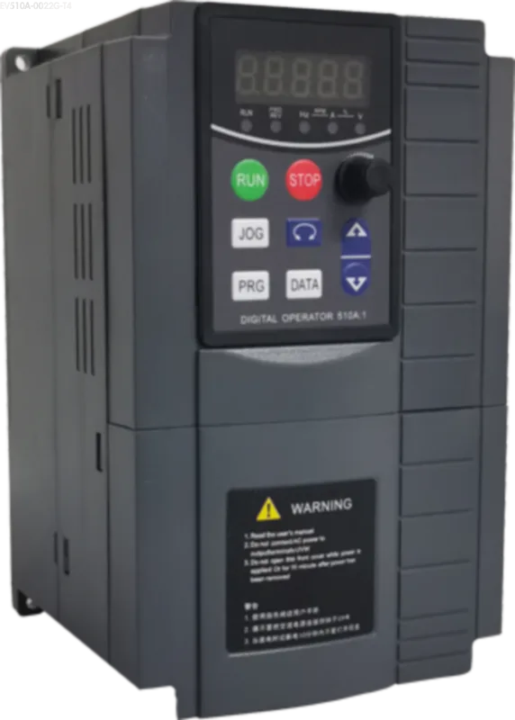
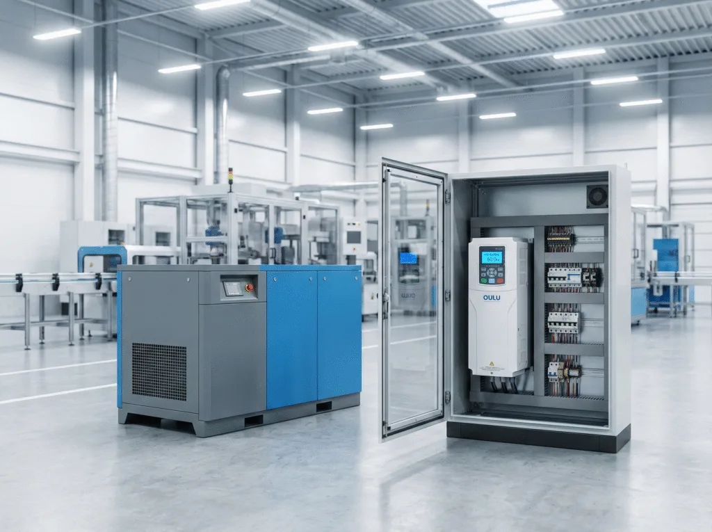
Troubleshooting Three Phase Current Imbalance in VFDs
Introduction
Dealing with a three phase current imbalance at the Variable Frequency Drive (VFD) output is a challenging issue that frontline electrical engineers frequently encounter. A current imbalance can lead to motor overheating, unexpected tripping, and severe mechanical stress. The root causes generally fall into three major categories: external load and cable faults, VFD internal hardware degradation, and incorrect parameter settings. This guide will break down each factor and provide actionable troubleshooting methods to help you resolve the issue efficiently.
What Causes a three phase current imbalance in VFDs?
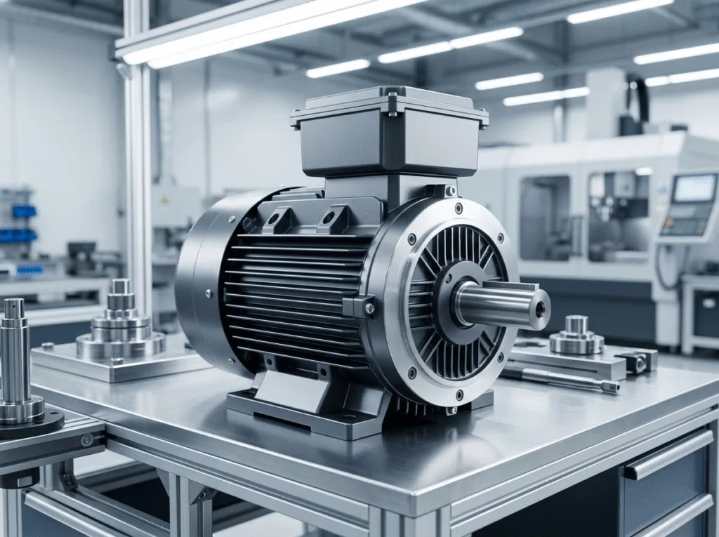
Motor Winding and Connection Faults
The motor is the first external factor to inspect. Typical motor-related issues that disrupt the current balance include:
- Winding Faults: Uneven turns in the three windings, phase-to-phase short circuits, or phase-to-ground short circuits.
- Terminal Box Issues: Dirt, thick dust, or rust on the motor’s terminal blocks can significantly increase contact resistance.
- Internal Taps: Welding errors on the internal winding taps during motor manufacturing or rewinding.
- Insulation Aging: Moisture or degraded insulation can cause short circuits between specific winding turns.
Cable Issues Affecting three phase current
Long transmission cables are highly susceptible to physical and electrical degradation. Common cable issues include:
- Broken Strands: Pulling or twisting forces during installation can break internal wire strands. This type of fault is hard to detect with a standard multimeter because the high resistance only manifests under heavy current loads.
- Insulation Damage: Damaged outer sheaths cause leakage currents and phase-to-ground shorts.
- Poor Quality Cables: Uneven wire diameters and poor conductivity in substandard cables directly cause unbalanced currents.
- Pro Tip: When the wiring between the inverter and the motor exceeds 50 meters (for 220V systems) or 100 meters (for 380V systems), high dv/dt will be generated inside the motor coil. This phenomenon amplifies cable-related imbalances.
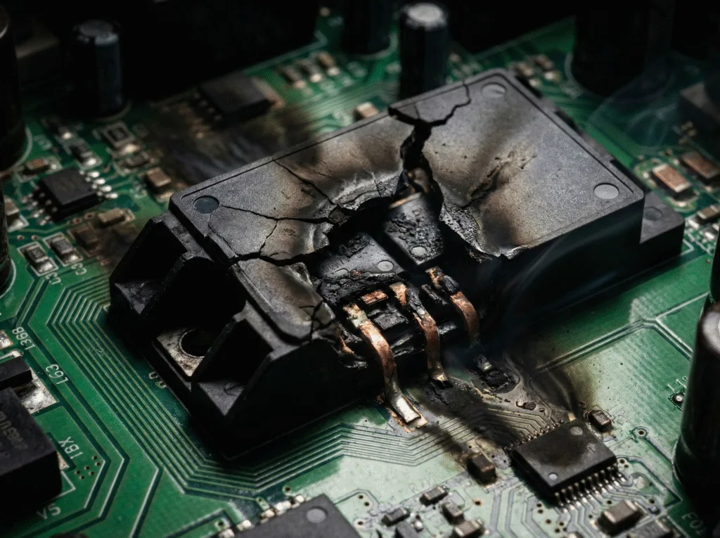
Internal VFD Hardware Faults
IGBT Aging and Six-Channel Drive Issues
If the motor and cables are in good condition, the problem likely lies within the VFD itself.
- IGBT Degradation: VFDs operating under heavy currents and high temperatures for many years (typically over 5–8 years) will experience IGBT semiconductor aging, altering internal resistance and causing unbalanced outputs.
- Six-Channel Drive Circuit: Aging electronic components on the drive board can lead to unbalanced drive voltages to the IGBTs. This is the most common internal cause.
- Motherboard PWM Signals: Though rare, faulty PWM signals from the motherboard can also cause imbalances.
Troubleshooting Method: For frontline engineers without advanced laboratory oscilloscopes, the most effective diagnostic approach is the “cross-validation method.” Swap the drive board or motherboard with a known good unit of the exact same model to instantly verify the fault source.
Parameter Setup and three phase current measurement

Auto-Tuning for three phase alternating current Motors
Incorrect motor parameters stored in the VFD can lead to poor control and current variations. Performing a motor auto-tuning process is highly recommended. It is necessary to correctly set the motor parameters to complete the automatic tuning. During auto-tuning, the VFD precisely measures the stator resistance, rotor resistance, mutual inductance, and leakage reactance. This allows the VFD to automatically compensate for IGBT conduction time deviations, ensuring highly accurate control over the motor.
Carrier Frequency and AC Output Reactors
Sometimes, the imbalance is caused by harmonic leakage currents interacting with distributed capacitance in the cables. To diagnose this, try lowering the carrier frequency. An increase in carrier frequency will result in an increase in the leakage current of the motor. If reducing the carrier frequency lessens the current imbalance, the issue is confirmed to be harmonic-related. However, reducing the carrier frequency might increase motor noise.
Solution Table: Dealing with High Carrier Frequency & Harmonics
Cable Length | Recommended Action | Expected Result |
|---|---|---|
< 50 meters | Lower Carrier Frequency | Reduced leakage current, potential noise increase. |
> 100 meters | Install AC Output Reactor | Suppresses high-order harmonics, peak voltages, and distributed capacitance effects. |
Frequently Asked Questions (FAQ)
What is three phase current?
Three-phase current is an alternating current (AC) system consisting of three separate electrical services with the same frequency and voltage amplitude, but with a phase difference of 120 electrical degrees between them. It is the global standard for industrial power transmission.
How to measure three phase current?
You can measure the current by using a digital clamp meter or a dedicated three phase current measurement device directly on the U, V, and W output cables of the VFD. Measurements should be taken while the motor is under normal load to accurately detect any imbalances.
How to calculate three phase current?
For a balanced three-phase system, the basic formula is I = P / (√3 × V × PF), where I is the phase current in Amps, P is the total power in Watts, V is the line-to-line voltage, and PF is the power factor of the motor.
Conclusion
Diagnosing a three phase current imbalance requires a systematic approach. By checking external motor windings and cables, ruling out VFD hardware aging, and optimizing parameters like auto-tuning and carrier frequency, engineers can successfully stabilize the system. Using the right diagnostic techniques, such as parts swapping and installing AC reactors for long cable runs, will ensure the longevity and efficiency of your industrial automation equipment.