VFD Braking Resistor Guide: 3 Functions & Selection Rules
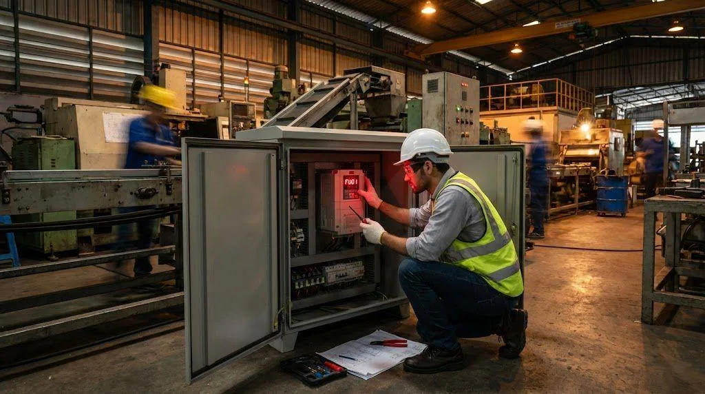
In actual industrial settings, the VFD braking resistor is a frequently overlooked yet critically important component. Many engineers wonder: “If my VFD already supports speed regulation, is installing a braking resistor still necessary?”
This article will systematically address this question from four perspectives: its operational mechanism, manufacturer configurations, applicable scenarios, and selection considerations.
Function of the VFD Braking Resistor
During VFD drives operation, the motor operates in two states:
- Electric Mode: Electrical energy is converted into mechanical energy.
- Generator Mode: When motor speed exceeds synchronous field speed, mechanical energy is converted back into electrical energy.
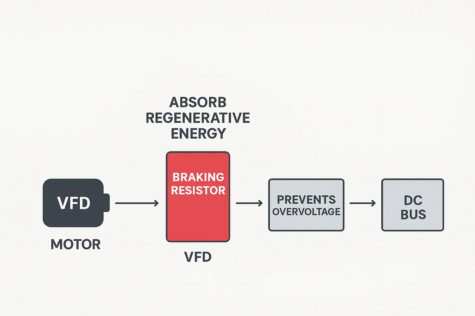
In this state, the motor feeds kinetic energy back to the VFD’s DC bus, causing the bus voltage to rise. Excessive voltage can easily damage the filter capacitors.
To prevent DC bus voltage rise, the VFD transfers excess energy via a chopper circuit to the VFD braking resistor for dissipation. This achieves system energy release and IGBT protection.
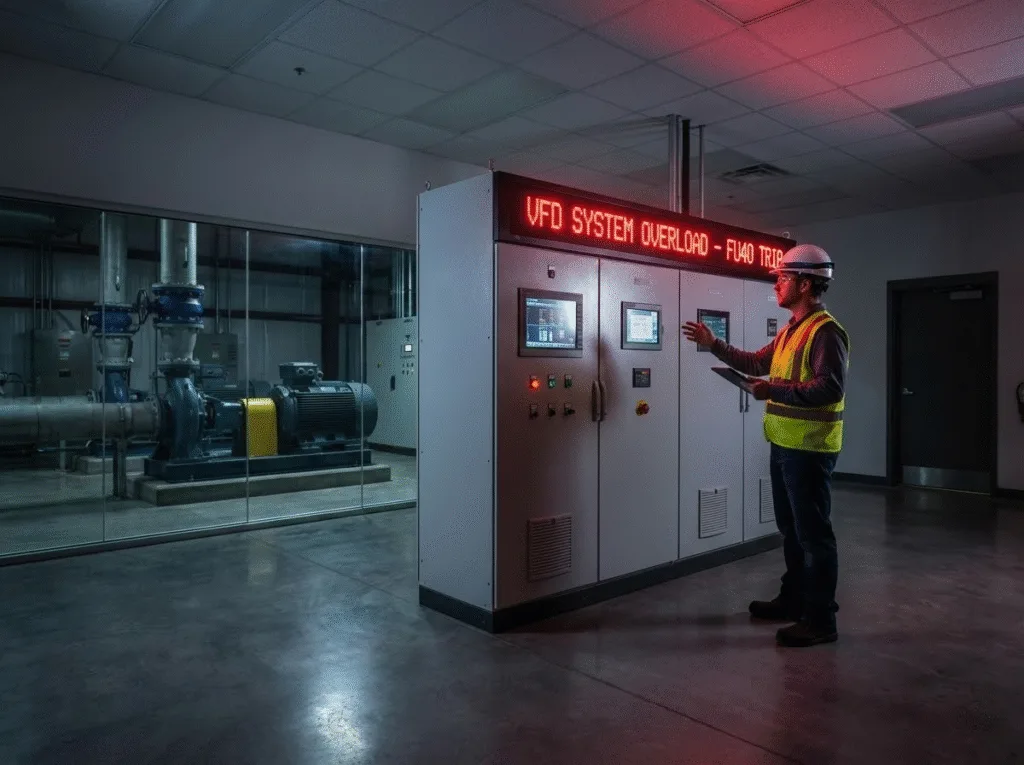
Without a braking resistor, excessive bus voltage would cause frequent overvoltage trips in the VFD, compromising operational stability.
Factory-Configured Braking in VFDs
Most manufacturers embed a low-power braking resistor within the VFD at the factory.
Its primary function is to handle standard deceleration and stopping processes, providing a braking torque percentage of approximately 10% to 20% of the rated torque.
For instance, when the stopping time is set to 10 to 30 seconds, the internal braking resistor can absorb the generated regenerative energy.
However, in applications involving high inertia, frequent braking, or high-speed stops, the internal resistor may prove insufficient. In such cases, an external VFD braking resistor must be considered.
When to Install an External VFD Braking Resistor or Braking Unit
An external braking resistor or braking unit should be installed under the following conditions:
1.Extremely short deceleration time
Examples include air compressors or centrifuges requiring shutdown within 2 seconds. Concentrated regenerative energy release during such deceleration may cause VFD overvoltage trips without sufficient braking resistor power dissipation.
2.Frequent or heavy-duty braking applications
In scenarios like cranes, elevators, downhill conveyor operation, or winding/rewinding systems, the motor enters a regenerative power generation state. Under these conditions, the built-in resistor’s power capacity is insufficient, necessitating an external braking resistor.
3.Bus Overvoltage Caused by Long Cables
When cables exceed 100 meters, issues like spike voltages, parasitic capacitance, and reflected wave effects can trigger VFD overvoltage problems. An external braking resistor effectively absorbs excess energy, stabilizes bus voltage, and protects IGBTs.
Key Considerations for VFD Braking Resistor Selection
1.Follow Manufacturer Recommendations
When selecting a VFD braking resistor, consult the original manufacturer’s manual and directly choose a matching model based on the percentage of rated torque. The built-in resistor can only provide 10%–20% of the braking torque, while an external resistor should provide at least 50% or more.
2.Calculate Resistance Value and Power Appropriately
- Resistance formula: R = U² / P
- Voltage U should be set to 700V (not 540V), as DC bus voltage typically rises during braking.
- Current I should be calculated based on IGBT rated current to prevent exceeding the VFD minimum braking resistance limit.
3.Prioritize Heat Dissipation and Cooling Coefficient
Even with correct parameters, insufficient cooling coefficient (braking resistor) may cause thermal overload and burnout if heat cannot dissipate promptly. For systems with frequent braking, resistors with forced air cooling or aluminum casing are recommended.
4.Consider Safety Margins and Installation Location
Apply a safety factor of 1.2 to 1.5 in power calculations and install in a well-ventilated area. Prolonged high temperatures may cause thermal degradation and resistance drift.
For a detailed introduction to brake resistor selection, please refer to my previous article, “VFD Braking Resistor Sizing: 3 Essential Steps and Formulas.”
Summary: When External VFD Braking Resistors Are Mandatory
In summary, installing an external braking resistor is recommended when any of the following conditions apply:
- Deceleration time is less than 5 seconds;
- Applications involve frequent or heavy-duty braking (e.g., hoisting, winding, conveying);
- Cable length exceeds 100 meters;
- The system frequently triggers VFD overvoltage trip alarms.
Installing an appropriate VFD braking resistor not only effectively absorbs regenerative energy and prevents bus overvoltage but also protects IGBTs and extends the inverter’s lifespan.
Therefore, in VFD drive system design, proper VFD braking resistor selection is critical to ensuring stable and safe equipment operation.