VFD Braking Resistor Sizing: 3 Essential Steps and Formulas
Hello everyone, today I’ll share practical experience on selecting VFD braking resistors. These resistors serve to dissipate energy and protect VFD drives, making proper selection critical for system safety and reliability. This article covers five key aspects—power calculation, resistance value determination, voltage rating selection, heat dissipation measures, and manufacturer recommendations—to help you quickly grasp the essentials of dynamic braking resistor selection.
Braking Resistor Power Calculation
First, how do we calculate the power rating for a VFD braking resistor?
In field engineering, overly complex models aren’t necessary. A concise, practical empirical formula offers greater practical value:
P = Motor Rated Power × Braking Duty Cycle × K
Where:
- Motor rated power: e.g., 7.5kW, 11kW, 55kW;
- Braking duty cycle: percentage of motor rated torque;
- 10% duty cycle: corresponds to 10% of motor rated torque;
- 30%–50% duty cycle: suitable for frequent braking applications;
- Higher duty cycle indicates greater braking torque;
- K (Safety Factor): Recommended range 1.2–1.5.
For example, in braking resistor power calculation:
- For short-duration braking (e.g., within 5 seconds), a 10% duty cycle suffices;
- For frequent braking, increase to 30% or higher.
Braking Resistor Ohm Calculation
The resistance value formula is: R = U² / P
Where:
- R: Braking resistor resistance value;
- U: VFD DC bus voltage;
- P: Braking resistor rated power.
In practical field applications, if the bus voltage is 540V and the power is 900W, then:
R = 540² / 900 = 324Ω.
However, note that during braking, the bus voltage often rises to 700–750V. Therefore, calculations should be based on the actual peak value.
This is a critical detail in how to calculate VFD braking resistor value.
Overvoltage Rating and Safety Factor
Many directly select the overvoltage rating based on the busbar rated voltage (e.g., 540V), but this is unsafe.
During braking, the busbar voltage may rise to 700–800V due to energy feedback.
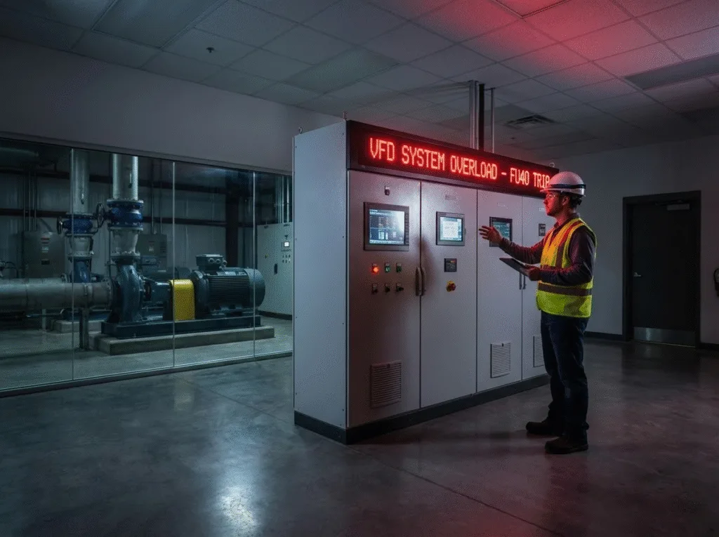
Therefore, the VFD braking resistor overvoltage rating should be selected at 800V or higher to prevent capacitor breakdown or resistor burnout.
This is also the most commonly overlooked aspect in braking resistor safety factor calculations.
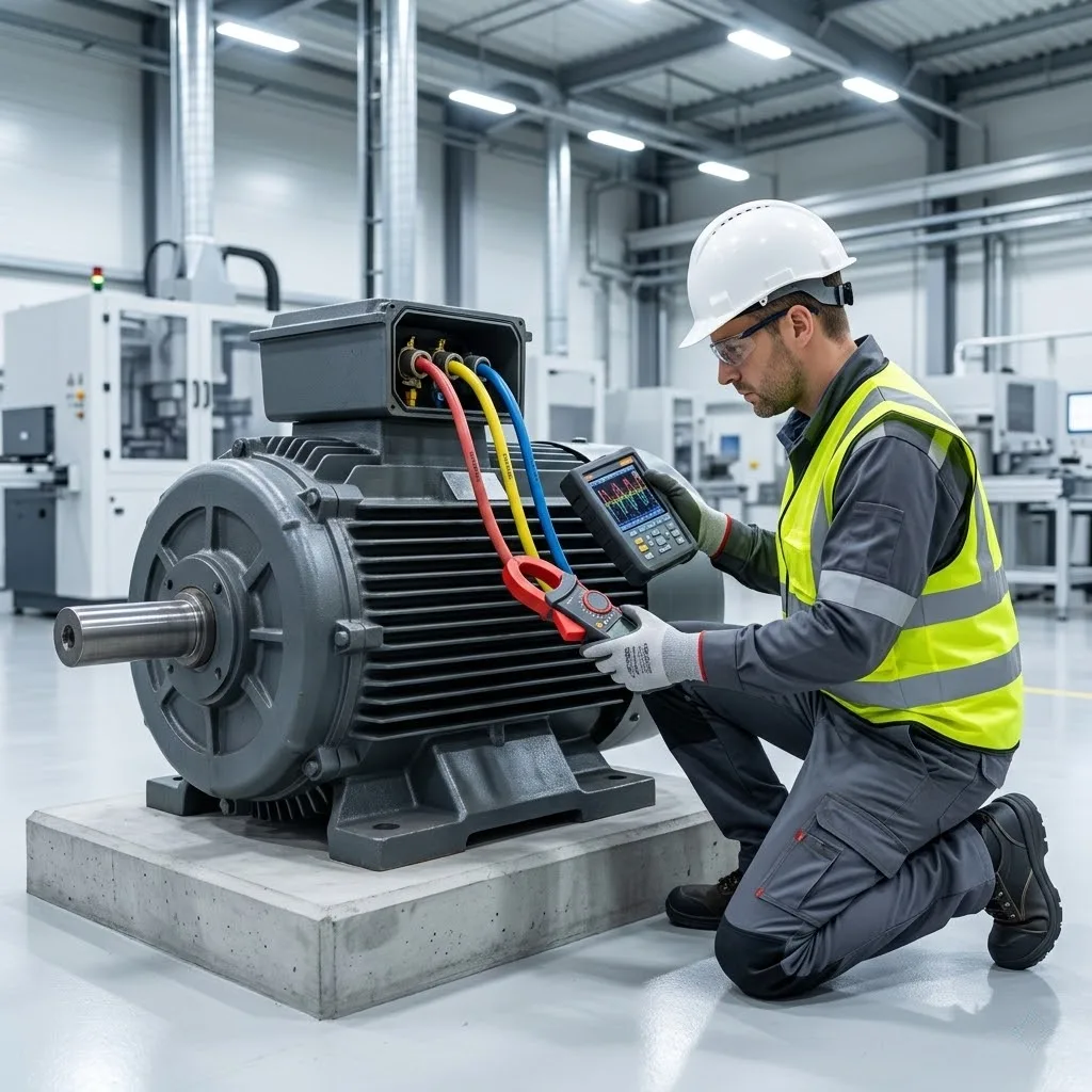
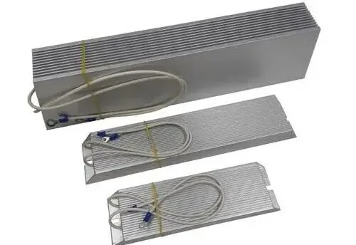
Braking Resistor Installation and Cooling
Regarding braking resistor installation and cooling, thermal performance is critical to longevity.
During frequent braking, the resistor temperature may reach 400–500°C.
To ensure safety:
- Select aluminum-cased resistors mounted on the VFD heat sink;
- Or employ a forced air cooling system directing airflow directly onto the resistor surface;
- Ensure the installation environment has adequate ventilation.
Inadequate cooling will compromise thermal management, potentially causing the resistor to glow red-hot or the casing to deform.
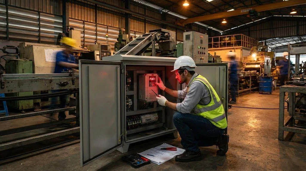
Manufacturer Recommendations
VFD braking resistor manufacturer recommendations vary by brand.
Most reputable manufacturers provide comprehensive selection tables in their product manuals, automatically matching resistor parameters (power rating, resistance value, part number, etc.) based on VFD power and braking duty cycle.
Users are advised to strictly follow the manufacturer’s VFD braking resistor selection formula to avoid purchasing substandard resistors.
Low-quality products exhibit high resistor tolerance and poor heat dissipation, making them prone to failure within a short timeframe.
Example Calculation
Example calculation for a 7.5kW three-phase 380V VFD:
- Braking duration: 5 seconds;
- Duty cycle: 10%;
- Safety factor K=1.2.
Calculation:
- P = 7.5 × 1000 × 0.1 × 1.2 = 900W
- R = √700² / 900 ≈ 544Ω
Rated voltage selection: ≥800V.
Final recommended specification: Power 900W, resistance approx. 540Ω, rated voltage ≥800V.
Summary: Proper Selection Ensures System Stability
The braking resistor is a critical component for absorbing regenerative energy in VFD drives, directly impacting DC bus voltage stability and system safety.
When selecting a resistor, comprehensively consider:
- braking resistor power calculation;
- ohm calculation;
- overvoltage rating;
- installation cooling;
- and manufacturer technical specifications.
Proper selection not only enhances braking resistor efficiency but also effectively extends the service life of VFD braking resistors, ensuring the safe and reliable operation of the entire system.