VFD Input Phase Loss: Why Does Phase Loss Trigger an Undervoltage Alarm? In-Depth Analysis and Single-Phase Operation Techniques
During industrial field commissioning, we often encounter a deceptive fault phenomenon: the VFD clearly experiences input phase loss, yet it triggers an undervoltage alarm instead.
Without understanding the underlying circuit logic, engineers may mistakenly attribute this to grid voltage fluctuations, leading to unnecessary troubleshooting. Today, we will deeply analyze the mechanism behind this phenomenon and share techniques for running a 3-phase VFD on single phase during extreme power shortages by leveraging the “over-sizing” approach.
The Heavy Load Illusion: Why Does VFD Input Phase Loss Become an Undervoltage Fault?
When operating under heavy load, a VFD input phase loss rapidly depletes the inverter’s DC bus voltage.
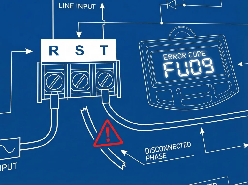
Core Logic: During phase loss, the rectifier bridge’s DC voltage ripple surges dramatically. Under heavy load consumption, filter capacitors cannot replenish charge fast enough, causing the average DC voltage to drop. When the voltage falls below the set threshold, the VFD prioritizes triggering an Undervoltage fault (displayed as FU09 on the EV510A) over a phase loss fault.
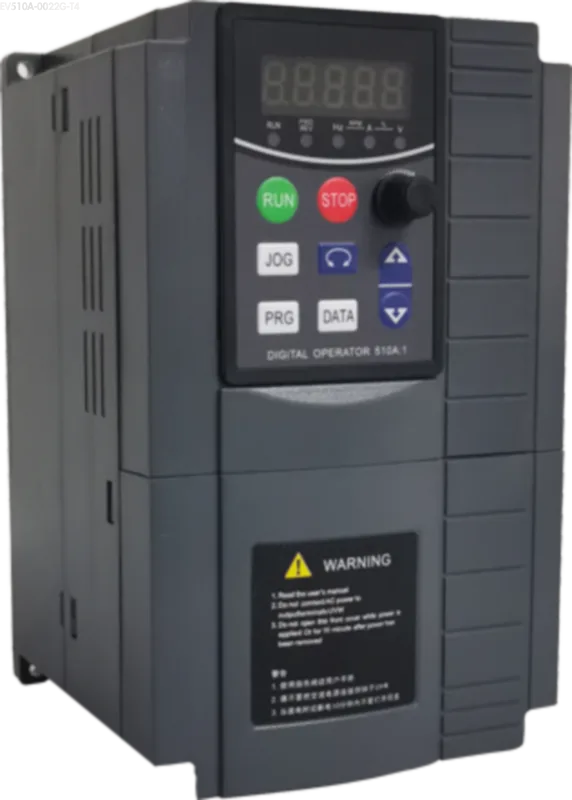
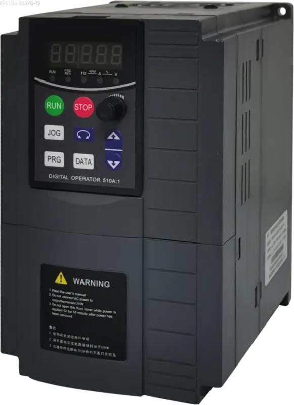
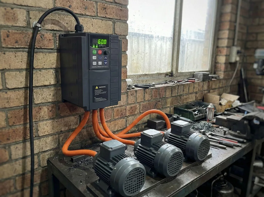
While some older VFDs lack direct phase loss detection, our EV510A series incorporates advanced detection algorithms. Users can enable this protection by configuring parameter P9-12 (Input phase loss protection selection). However, under default settings or when protection is disabled, heavy-load phase loss often manifests first as undervoltage. Therefore, upon encountering an undervoltage alarm during heavy load operation, immediately inspect the input power supply for phase loss.
Industrial Case Study: Addressing Power Cutoffs with Sizing VFDs for Single-Phase Input
This is a classic industry example. Around 2010, industrial power cutoffs often reduced three-phase power to two-phase (effectively causing VFD input phase loss). To maintain production, many factories adopted an “over-sizing” strategy.
Method: Purchase a high-power VFD (e.g., 45kW or 55kW) to drive low-power motors (e.g., 5.5kW or 7.5kW).
- Principle: Despite phase loss in the input power, the VFD’s large internal capacitors could smooth the DC bus voltage. This sufficient capacity supported the operation of small loads.
- Result: Even under severe VFD input phase loss conditions, multiple small motors can continue normal production. This demonstrates that VFDs can operate reliably under single-phase input provided derating principles are followed (typically derating by 50% or more).
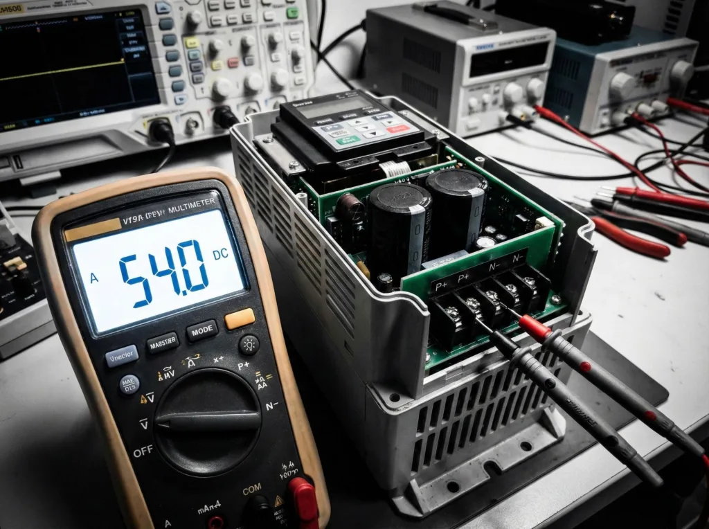
Lab Secret: Monitoring DC Bus Voltage for Single-Phase Testing
Our training center faced a persistent lack of three-phase power. Our solution involved stepping up single-phase 220V to single-phase 380V via a transformer, directly supplying the VFD’s R and T terminals.
Technical Key: The rectified DC voltage from a single-phase 220V is only around 310V. However, 380V-rated VFDs (like the EV200-T4) require approximately 540V DC bus voltage for normal operation. By boosting to single-phase 380V, the rectified DC bus voltage reaches the 540V standard.
During light-load or no-load commissioning phases, this VFD input phase loss condition does not affect functional testing. You can monitor the voltage status in real-time by checking parameter d0-02 (Bus voltage). As long as the voltage remains stable, commissioning can proceed normally.
Conclusion
Ultimately, the manifestation of VFD input phase loss faults is entirely dependent on the load rate. Under light loads, large capacitors mask the absence of a phase; under heavy loads, the DC bus voltage drop directly triggers the under-voltage protection.
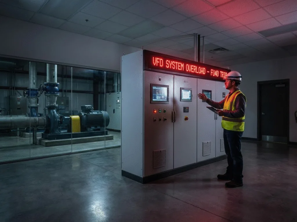
If you encounter such power quality issues on-site, beyond inspecting the wiring, we strongly recommend using drives with independent input phase loss protection, such as our EV510A series. This feature allows users to enable or disable the protection via parameter P9-12 flexibly. Combined with the precise FU12 fault code indication, it strikes the optimal balance between protecting equipment and maintaining production.