VFD Input Reactor Overheating: 6 Causes and Solutions
Introduction
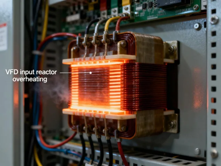
Hello everyone, today we will analyze a typical on-site technical case related to VFD input reactor overheating. This problem is relatively uncommon, but once it occurs, it usually comes with complex fault phenomena, so it is worth a systematic explanation.
The on-site situation is as follows:
- The VFD input reactor overheats seriously, even accompanied by squeaking noise.
- The output reactor temperature is normal.
- The braking resistor reaches 200–300℃;
- Measured input voltage and current appear normal.
Many engineers may wonder: if voltage and current are normal, why does VFD braking resistor overheating occur together with input reactor abnormalities?
Root Cause of Input Reactor Overheating
The key reason for VFD input reactor overheating is not the RMS current, but the harmonic current and high-frequency voltage. Ordinary multimeters or clamp meters can only measure RMS values but cannot reflect the real impact of high-frequency harmonics.
When the IGBT inside the VFD switches at high frequency, a large number of 5th, 7th, 11th, and 13th harmonics are generated. These harmonic currents overlap in the input reactor, causing the magnetic circuit core to approach magnetic saturation. At this point, mechanical vibration occurs between the coil and the silicon steel sheets, resulting in the typical phenomenon of “why is my VFD input reactor humming?”
Reason for Serious Braking Resistor Overheating
The braking resistor reaching hundreds of degrees Celsius indicates a large braking current or frequent braking. During frequent braking, DC bus voltage fluctuation continuously occurs. The DC bus voltage is reflected into the grid through the rectifier bridge diodes, forming transient voltage and high-frequency current pulses. These pulses eventually increase the thermal load of the input reactor.
Therefore, VFD braking unit issues and VFD input reactor overheating are interrelated and must be analyzed together.
Other Possible Secondary Factors
Besides the main reasons of harmonics and braking unit, the following issues should also be checked:
- Undersized input reactor, with insufficient rated current;
- Insulation aging, inter-turn short circuits, or loose iron core;
- VFD filter capacitor aging, leading to unstable DC bus voltage;
- Input power supply voltage imbalance (VFD input voltage unbalance);
- Grid harmonics are causing waveform distortion.
- Poor cooling or blocked ventilation.
These secondary factors are often overlooked but can aggravate overheating.
Troubleshooting and Solutions
To solve VFD input reactor overheating, the following directions can be considered:
- Optimize the braking unit: properly raise the DC bus overvoltage action threshold to reduce frequent switching.
- Check braking resistor selection: ensure power rating and resistance are suitable to avoid long-term high-temperature operation.
- Use an oscilloscope or harmonic analyzer: measure 5th, 7th, 11th, and 13th harmonics, and confirm their impact on the input side.
- Check the reactor condition: inspect for short circuits, winding problems, or loose iron core.
- Check power supply quality: apply VFD harmonic mitigation measures if needed, such as input filters or adjusting line impedance.
- Confirm cooling conditions: ensure airflow is unobstructed to avoid local overheating.
Only by approaching from a VFD fault diagnosis perspective, considering both the braking unit and input reactor, can the overheating and noise problems be completely resolved.
Conclusion
VFD input reactor overheating is not caused by a single fault, but by the combined effects of harmonics, grid conditions, braking unit operation, and aging components in a variable frequency drive system. When performing VFD troubleshooting, engineers should not rely only on RMS values of voltage and current, but should use oscilloscopes and other tools, combined with harmonic analysis, capacitor condition, and braking unit settings, to thoroughly identify the root cause and eliminate the problem.