VFD Installation Tips and Troubleshooting Guide
Let’s talk about VFDs today – the “star player” in electrical control systems! Responsible for motor speed control and energy saving, VFDs are absolutely critical. If an electrical control system were a stage, VFDs would undoubtedly be a lead performer. Mastering VFD technology will empower you to tackle related challenges with confidence!
VFD Operating Principles
(A) Fundamental Theory
A VFD essentially adjusts motor speed and torque by modifying the power supply frequency and voltage. Remember this key formula:n = 60f(1-s)/p (n: speed [rpm], f: frequency [Hz], s: slip ratio, p: pole pairs) This equation is the VFD’s working principle – understanding it reveals how VFDs function.
(B) Operational Stages
DC Bus: Filters and stabilizes DC voltage – giving the current a “massage” to prepare it for the next stage.
Inversion: Uses PWM (Pulse Width Modulation) to convert DC back to variable frequency AC for motor control – essentially equipping electricity with “transformer” capabilities.
(C) Key Functions
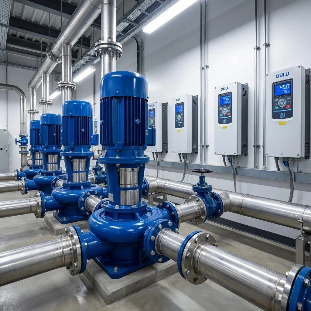
Energy Efficiency: Automatically optimizes power output based on load – acting as an intelligent “VFD energy saver.”
Protection: Safeguards against overcurrent, overvoltage, undervoltage, overheating – providing 24/7 “VFD protection features.”
Installation Guidelines
(A) Environmental Requirements
Cooling Requirements: Maintain vertical installation with ≥10cm clearance for proper heat dissipation.
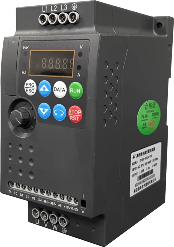
(B) Wiring Standards
Motor Output (U/V/W): Use shielded VFD output cables ≤50m (add reactor if exceeding).
Grounding: Grounding resistance ≤10Ω – create a safe “home base” for the VFD.
Control Signals: Use shielded signal cables, separated from power lines to reduce EMI noise.
(C) Peripheral Devices
Braking Resistor: Enables rapid motor deceleration – essential for “emergency brakes.”
EMI Filter: Reduces electromagnetic interference – maintaining “EMC compliance.”
Operation & Commissioning
(A) Parameter Configuration
Control Modes: Choose V/F control (constant torque) or vector control (high precision).
Frequency Settings: Via keypad, analog signal input (0–10V/4–20mA), or Modbus/Profibus communication.
Accel/Decel Times: Adjust by load inertia – find the “Goldilocks zone” between efficiency and safety.
(B) Commissioning
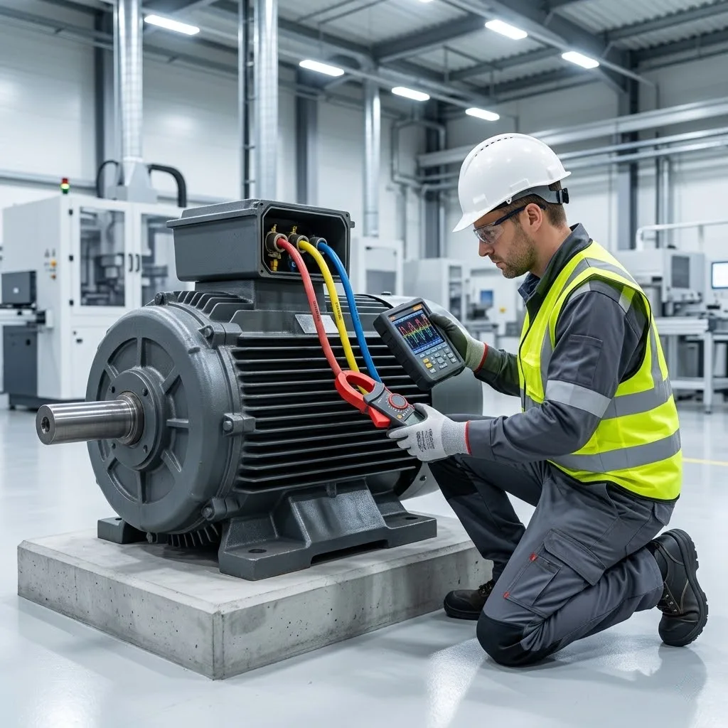
Load Test: Increase frequency while observing current/speed – a “VFD load simulation.”
Fault Diagnosis: Use VFD error codes (e.g., OC/OV/GF) for quick VFD troubleshooting – the VFD’s “SOS signals.”
(C) Maintenance
Pre-charge capacitors before restarting after long downtime.
Common Issues & Solutions
Issue | Causes | Solutions |
|---|---|---|
Overcurrent (OC) | Rapid acceleration, short circuit | Extend acceleration time, inspect insulation |
Overvoltage (OV) | Abrupt deceleration, faulty braking | Adjust deceleration time, check brake resistor |
Motor Stalling | Zero frequency setting, wiring errors | Verify parameters & connections |