Top 10 Causes of VFD Overcurrent Fault
What Is a VFD Overcurrent Fault?
VFD overcurrent fault refers to the emergency protection response triggered when the VFD detects a transient current exceeding 150% of the rated value (lasting for over 300 μs). Upon detecting an overcurrent, the IGBT output pulses are immediately blocked—similar to the fuse protection mechanism in power systems. When this anomaly is detected (VFD fault codes, e.g., FU-02; actual codes should refer to the equipment manual), the current transformer triggers protection within 0.1 ms with ±1% accuracy, preventing IGBT module burnout (junction temperature exceeding 175°C) or motor insulation carbonization risks. Such VFD faults, which account for 42% of VFD shutdown events, are precisely the core faults that can be proactively prevented through parameter optimization and hardware detection.
Top 10 Common Causes of VFD Overcurrent Fault
1. Excessive Motor Load
Variable drive motors driving high-inertia loads (such as variable frequency drive pumps when the impeller suddenly encounters stalling or cavitation water hammer during startup) experience a sudden increase in mechanical resistance, forcing the output torque to exceed the 150% limit. To maintain the set speed, the VFD will continue to increase the current. When the current exceeds 200% of the rated value and continues for more than 500 ms, the VFD overcurrent fault will inevitably be triggered. Checkpoints include the brake status of the fan, blockage of the pump housing flow path, and abnormal friction torque in the transmission system.
2.Short Circuits
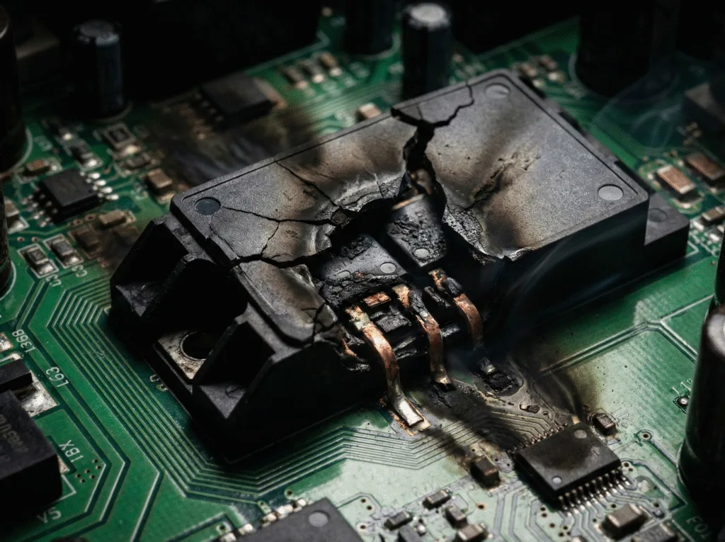
Output phase-to-phase/ground short circuits cause currents to far exceed rated values (>1000%), potentially causing VFD components (IGBT/capacitors) to explode and instantly trigger VFD fault codes—the most serious type of VFD fault.
3.Improper VFD Settings
When the acceleration time is too short (<0.5s) or the current limit is >180%, the components of a VFD (such as IGBT/monitoring unit) will misjudge the load characteristics, causing VFD drives to frequently trigger VFD overcurrent fault.
4.Motor or Cable Issues
Variable frequency motor winding interturn short circuit (equivalent resistance reduced by 20 times) or VFD electrical cable insulation aging (ground leakage > 5 mA), resulting in current waveform distortion (THD > 25%) and three-phase imbalance > 5%, directly triggering a VFD fault.
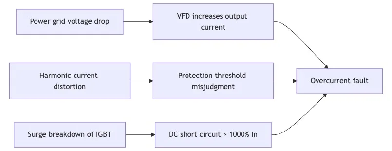
5.Power Quality Issues
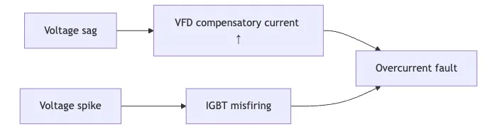
When VFD harmonics (>30% THDi) pollute the power grid, current transformer sampling distortion (deviation >15%) occurs. At this point, if a sudden VFD voltage spike (>6kV/3kA surge) occurs and the VFD surge protection response delay is >10μs, it will cause the IGBT module to break down, resulting in a DC bus short circuit. For VFD systems in HVAC applications with frequent start-stop cycles, a voltage drop exceeding 15% can force the output current to surge compensatorily by over 200%, directly triggering a VFD overcurrent fault.
6.Internal VFD Failure
VFD components Hardware damage (such as IGBT gate breakdown, DC capacitor ESR increase > 50%, or current transformer zero drift) causes components of a VFD to output abnormal current increases—drive board signal distortion causes phase current to suddenly increase > 200%. This non-linear fault forces overcurrent protection to trigger even when the VFD mechanical load is normal.
7.Load Deceleration
Variable speed drives (VSDs) may experience rapid deceleration (e.g., when the damper of a centrifugal fan suddenly closes). During such deceleration, the VSD motor transitions to generator mode due to inertia, causing regenerative energy to flow back into the system and causing the DC bus voltage to surge above 120%. This forces the IGBTs on the inverter side to withstand reverse current surges, triggering a VSD overcurrent fault. Typical scenarios: hoisting mechanism free-falling, conveyor line emergency braking (when the braking resistor capacity is insufficient).
8.Input Power Spike
Lightning strikes or grid switching can cause a VFD voltage spike (>130% of rated voltage), resulting in overvoltage of the DC bus capacitor in the frequency drive inverter, which leads to uncontrolled conduction of the IGBT gate charge and an instantaneous current overshoot of >180%. When the VFD surge protection response is >100μs, an overcurrent fault is triggered.
9.Rapid Load Changes
When vfd drives encounter a blockage in the feeder or conveyor of a mixer, the load torque suddenly increases by more than 150% within 0.2 seconds. The 10ms adjustment cycle of the variable frequency drive motor control cannot respond instantaneously, forcing the current to exceed the 200% threshold. If the overload tolerance time of the VFD motor is less than 5ms (such as a permanent magnet motor), it will trigger a VFD overcurrent fault.
10.Grounding Issues
When the grounding resistance exceeds 5Ω or the PE line is loosely connected, the leakage current (>50mA) caused by the vfd ground fault cannot be effectively discharged. The control system may misinterpret it as a load-side short circuit. This false current, when added to the actual operating current, can exceed 150% of the rated value and directly trigger a vfd overcurrent fault.
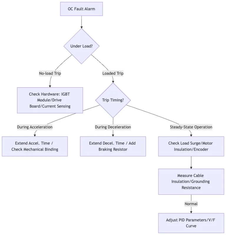
Troubleshooting Steps:
1.Inspecting the Load
Check for impeller jamming (idle torque > 15% of rated value) in the VFD water pump or whether the variable frequency motor is overloaded (current > 110% and lasting > 10 seconds). Record the current curve during the start-up and shutdown phases—if there is a sudden increase of 150% within 0.5 seconds accompanied by mechanical vibration (exceeding 4 mm/s), this confirms that the mechanical load abnormality is the root cause of the VFD overcurrent fault.
2.Review VFD Settings
When performing VFD drive troubleshooting, verify the following:
- VFD control core parameters:
- Acceleration time (≥ motor inertia time constant × 3)
- Current limit (110%-150% FLA)
- Variable frequency drive motor control compatibility:
- Carrier frequency (8-12kHz to avoid resonance points)
- Motor FLA value (compare with nameplate ±5%)
- Abnormal signals for VFD settings:
- Output frequency oscillation > ±2 Hz
- DC bus fluctuation > ±15%
- Parameter mismatch may cause uncontrolled current surges. Real-time monitoring of voltage/current tracking characteristics is required (alarm triggers if deviation exceeds 10%).
3.Inspect Motor and Cables
Test the phase-to-phase resistance deviation of VFD motor windings (>±2%) and cable insulation (megohmmeter ≥5MΩ). Loose VFD electrical terminals (contact resistance >10mΩ) or insulation damage will cause leakage current >50mA. A broken shielding layer in the VFD cable can cause high-frequency interference and trigger overcurrent protection. This hidden issue must be identified by scanning the resonant frequency deviation (>±5kHz) using an LCR meter. In cases of deep damage such as winding interturn short circuits, professional variable frequency drive repairs must be performed.
4.Test for Shorts
Perform a three-step inspection:
- Turn off the power and check for electricity → Use a multimeter to measure the resistance between the U/V/W phases (a difference of >±1% is abnormal)
- Use a megohmmeter to test → Measure the resistance between the phase line and ground (a value <1MΩ indicates a ground fault)
- Disconnect and test → Isolate the components of a VFD (IGBT module resistance < 10Ω indicates breakdown). If a short circuit is detected, follow the VFD troubleshooting flowchart to replace damaged components. Phase-to-phase short circuits must report VFD fault codes, accounting for 33% of all VFD faults, especially VFD overcurrent faults, which require priority attention to eliminate this risk.
5.Monitor Voltage
Capture input-side transients such as VFD voltage spikes (>130% peak) or drops (<80% lasting 100 ms) using an oscilloscope. Such fluctuations force the VFD inverter to increase current compensation power, causing overcurrent.
Synchronous detection:
- Are VFD harmonics >20% (current sampling distortion)?
- Is the VFD surge protection response <25μs (IEEE C62.41 standard)? When voltage fluctuations occur, DC bus ripple >±15% indicates a warning of grid abnormalities.
Troubleshooting process:
6.Test Components Separately
Disconnect the AC motor VFD from the load and connect a resistive load to simulate the VFD for the exhaust fan operation (e.g., 30% power). If the overcurrent disappears, the fault source is on the mechanical side; otherwise, disassemble the machine to inspect the VFD components:
- IGBT module (use a multimeter to measure the C-E terminal resistance; if it is <10Ω, it is broken down)
- Driver board optocoupler (if the delay exceeds 3μs, replacement is required)
- DC capacitor (if the ESR exceeds 200% of the rated value, it is deemed faulty)
- Severe damage requires VFD drive repair and replacement of the power unit.
7.Inspecting the VFD Internally
When the ambient temperature exceeds 40°C, the VFD in HVAC systems must be derated by 15% to prevent insufficient heat dissipation from triggering overcurrent protection. EMI interference sources (such as crosstalk from nearby VFDs in the 30 MHz to 500 MHz frequency range) can cause false triggering, necessitating the installation of an RFI filter (with insertion loss exceeding 40 dB). When the closed-loop resistance of the grounding network exceeds 5Ω (avoid series grounding), stray currents may induce abnormal detection currents exceeding 100mA. Such external factors account for 18% of VFD overcurrent faults.
Conclusion — Preventing Overcurrent Faults in VFD Systems
Preventing and controlling VFD overcurrent faults requires multi-dimensional coordination: by reasonably setting dynamic response parameters, systematically performing VFD maintenance (regularly inspecting key components and cooling conditions), and monitoring abnormal current trends in real time, combined with in-depth analysis of VFD fault codes through VFD troubleshooting, the fault rate can be significantly reduced. The core lies in predictive maintenance of VFD components and precise adaptation to load characteristics, keeping overcurrent risks within industrial safety standards.