VFD Motor Failure: The Three Hidden Killers Behind Frequent Burnouts Despite Low Current
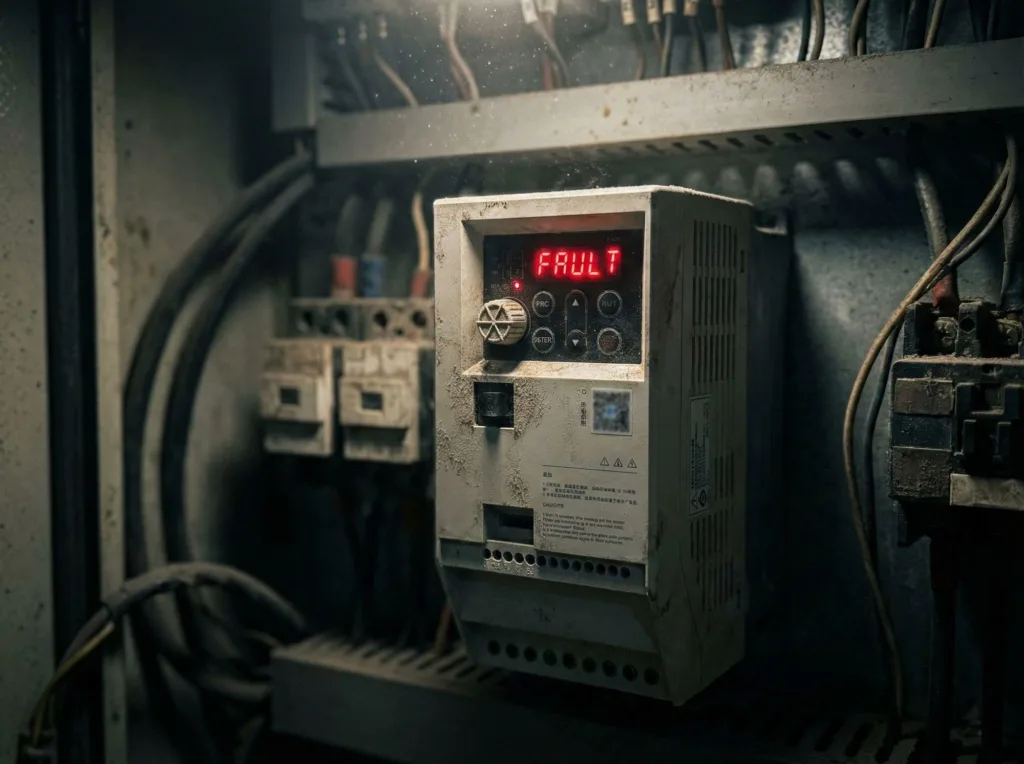
In industrial settings, we often encounter a highly deceptive type of VFD motor failure: motors that burn out frequently despite operating at currents far below their rated values.
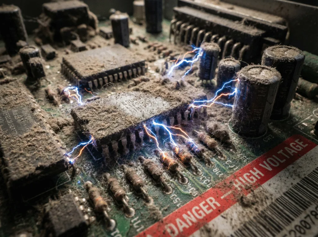
This isn’t ordinary overload—it’s an invisible killer triggered by high-frequency harmonics. Many engineers have investigated overcurrent and overload protections only to find all parameters normal, ultimately leaving them helpless. Today, I will peel back the layers and delve into the root causes of this highly technical failure from three microscopic dimensions: insulation breakdown, shaft current, and bearing electrocorrosion.
Before diving into the analysis, ensure you have implemented the most fundamental standard: equip each motor circuit with independent start/stop control and protection devices. If this step is already in place, the problem lies in deeper layers of “power quality.”
In-Depth Analysis of Three Hidden Causes Leading to VFD Motor Failure
When current readings appear normal, yet the motor still fails, we typically encounter the following three atypical scenarios of VFD motor failure.
1. Insulation Breakdown Caused by Long Cables
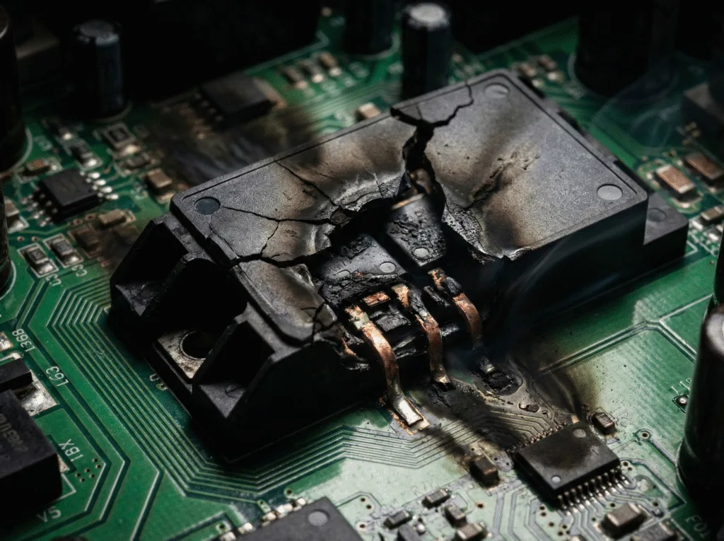
This is the most common first cause of failure: Upon disassembling a burned-out motor for inspection, a ground short circuit or phase-to-phase insulation breakdown is discovered.
Failure Logic: This type of VFD motor failure typically occurs with extended motor cables (e.g., exceeding 100 meters). The inverter outputs high-frequency PWM waves containing substantial harmonics. During transmission through long cables, harmonic superposition generates a reflective wave phenomenon, causing voltage surges at the motor terminals.
Based on our field test data, at cable lengths around 100 meters, the superimposed spike voltage can reach as high as 2000V to 2500V. This voltage far exceeds the withstand voltage limit of standard motor insulation. Over time, the insulation is repeatedly punctured like a needle prick, eventually leading to insulation breakdown and causing severe VFD motor failure.
2. Shaft Voltage Causing Bearing “Bluish Discoloration”
The second scenario is even more catastrophic: Upon disassembling the motor, the shaft is found scorched blue, with bearings completely burned out and disintegrated.
Cause Analysis: This is not mechanical friction overheating, but a classic shaft voltage issue. Due to unbalanced three-phase voltage (common-mode voltage) output from the VFD, voltage is induced at both ends of the motor shaft. When this voltage accumulates to a certain level, it breaks down the oil film within the bearings, forming a loop current (shaft current). Although this current is relatively small, it generates high temperatures at minute contact points, instantly melting metal. This causes the bearings to turn blue and disintegrate, ultimately leading to mechanical seizure and VFD motor failure.
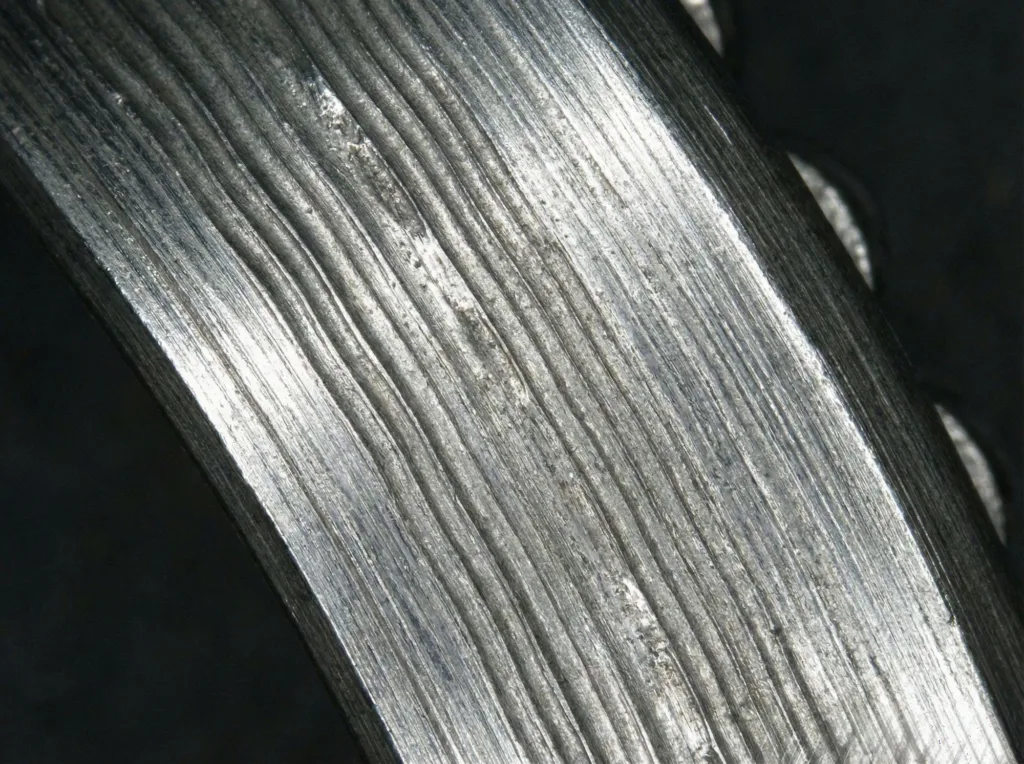
3. Bearing Fluting (Electrical Erosion) and “Washing Board Patterns.”
The third scenario is a variant of the second, but its characteristics are more subtle. Upon inspecting the bearings after motor failure, though they are disintegrated, distinct, orderly “washing board patterns” are visible within the raceways.
Failure Characterization: This is a classic case of electrical erosion (Electric Erosion). High-frequency shaft currents discharge repeatedly between the bearing raceway and balls, etching grooves into the raceway like miniature spark erosion (i.e., bearing fluting).
Once this pattern forms, the bearing generates severe vibration during high-speed operation, accelerating wear and producing high temperatures, ultimately leading to bearing seizure. This is also a significant yet often overlooked cause of VFD motor failure.
Ultimate Solution: Zero-Cost Adjustment with Hardware Enhancement
For the three types of VFD motor failures caused by harmonics and voltage spikes, I summarize two major solution categories.
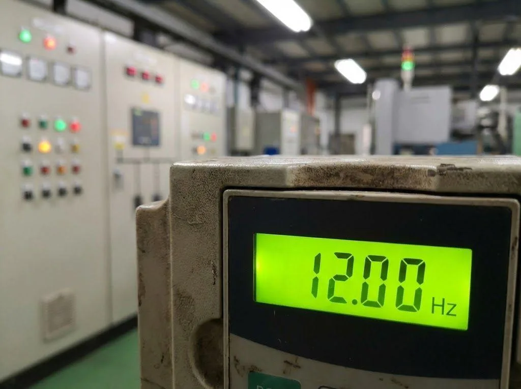
1. Zero-Cost Solution: Adjusting Carrier Frequency
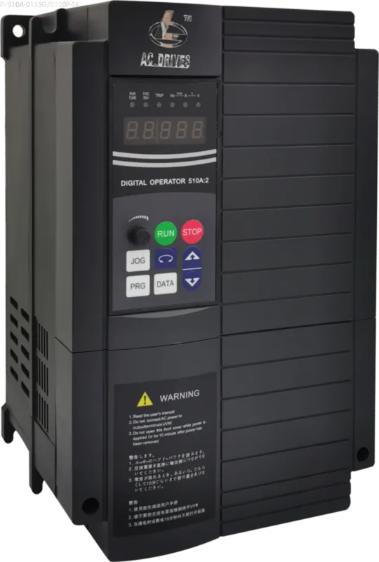
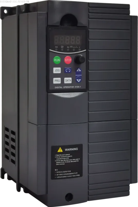
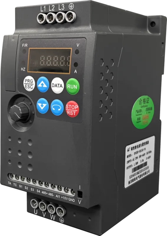
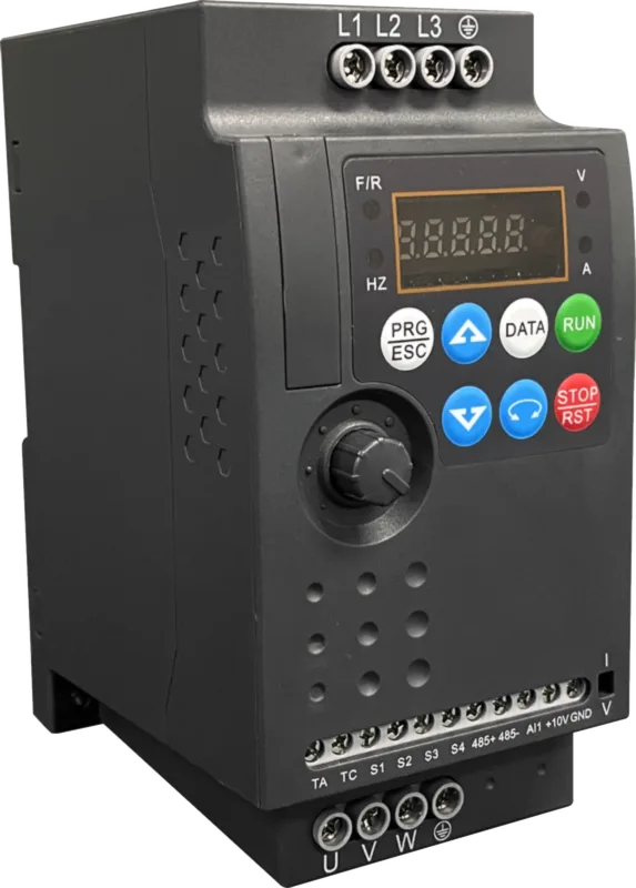
This is the first troubleshooting step. Refer to parameter P0-15 (Carrier frequency) in the EV510A User Manual or P0-15 in the EV200 User Manual, and attempt to lower the carrier frequency.
- Procedure: Gradually reduce the carrier frequency from its default value (e.g., 8kHz or higher).
- Principle: Lowering the carrier frequency directly reduces the number of pulse switching cycles per unit time, thereby decreasing harmonic superposition frequency. With fewer harmonics, spike voltages naturally diminish. As long as voltage peaks remain below insulation withstand voltage or bearing breakdown thresholds, the risk of VFD motor failure is significantly mitigated.
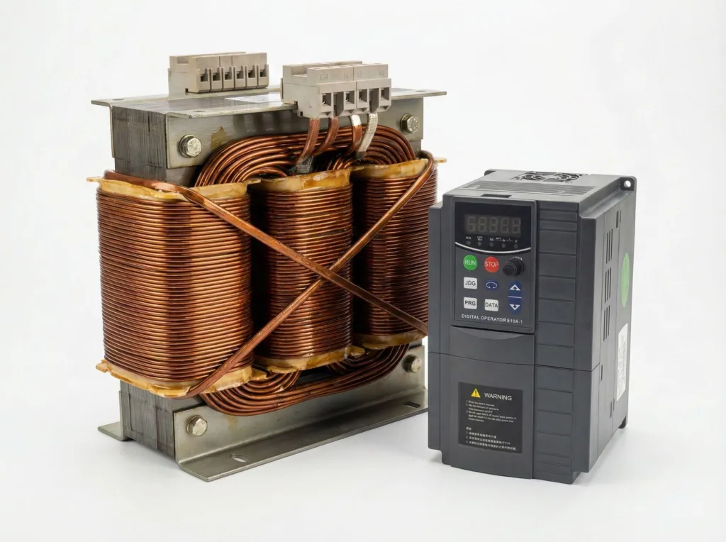
2. Hardware Solution: Install an Output Reactor
If lowering the carrier frequency yields limited results, or if excessive frequency reduction is prohibited due to noise requirements, physical measures must be employed. Our VFD Selection Guide specifically recommends installing an output AC reactor when the distance between the VFD and motor exceeds 100 meters.
- Action: Install an output reactor on the VFD output side.
- Rationale: Output reactors effectively suppress harmonics, smooth voltage peaks and troughs, and “flatten” voltage spikes. This is the most thorough solution for preventing long-cable insulation breakdown and bearing electrocorrosion, fundamentally guarding against VFD motor failure.
Conclusion
The core challenge in addressing persistent VFD motor failures lies in controlling output voltage quality. Whether it’s insulation breakdown or bearing fluting, the root cause is peak voltages triggered by high-frequency harmonics.
As field engineers, our first choice is zero-cost carrier frequency adjustment. If the effect is limited, we must decisively install an output reactor. For long-distance transmission applications, we recommend referring to our EV510A or EV200 series selection guides to reasonably configure peripheral accessories. This physically cuts off the invisible damage of harmonics to the motor, ensuring long-term equipment operation.