VFD Overcurrent Fault During Constant Speed Operation: In-Depth Troubleshooting and Solutions
Today we tackle a persistent industrial challenge: VFD overcurrent fault during constant speed operation.
Many ask me how to fix VFD overcurrent faults, especially when they occur during constant speed operation—a particularly complex scenario. This issue involves numerous variables, from sensor inaccuracies to hidden inrush currents. Drawing on over three decades of VFD R&D and field commissioning experience, I’ve broken down this fault into an in-depth series to help you thoroughly understand VFD troubleshooting methodologies.
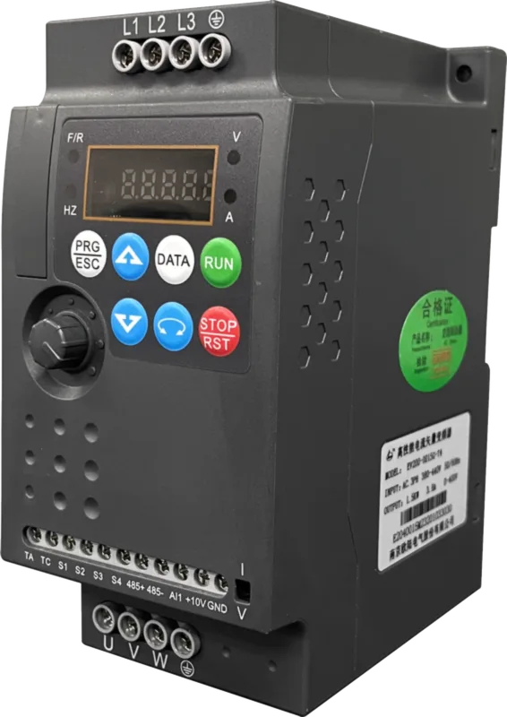
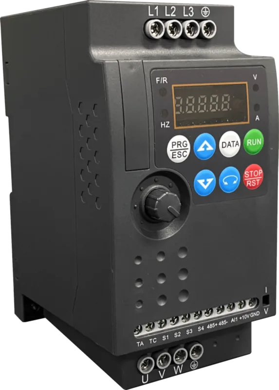
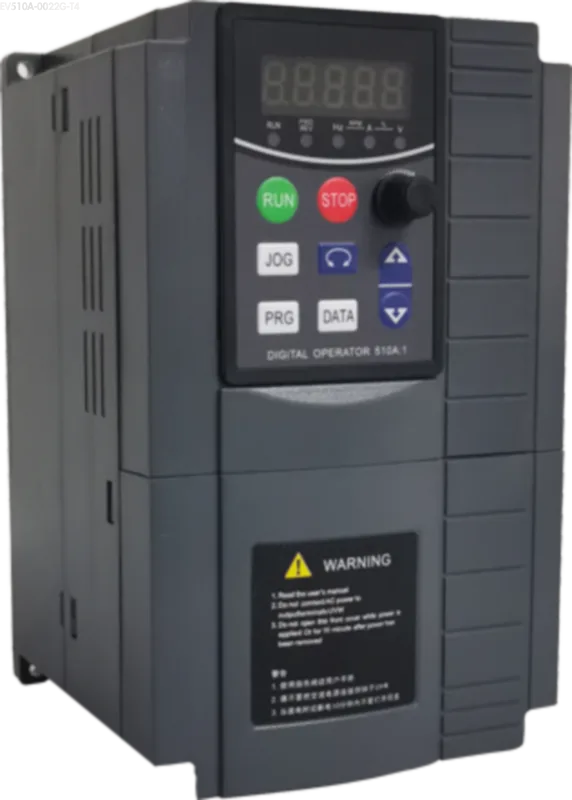
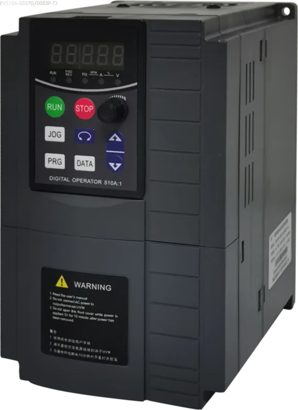
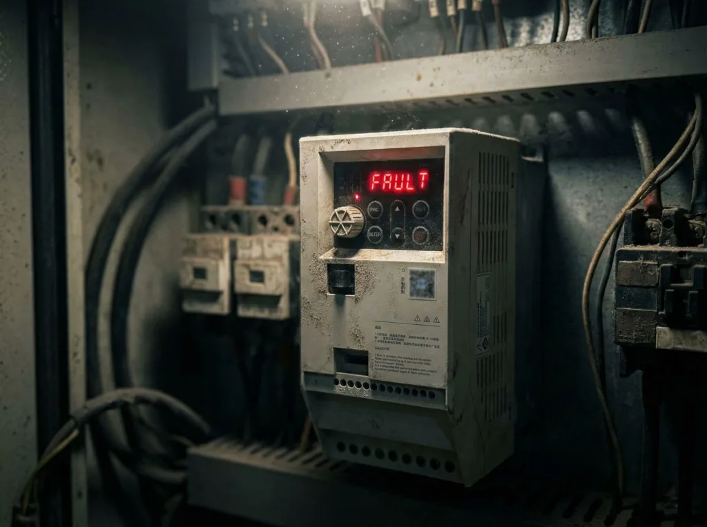
In our EV510A or EV200 series manuals, this fault typically displays as FU04 (Constant Speed Overcurrent). When your equipment suddenly trips during normal operation due to a VFD overcurrent fault at constant speed, immediately follow this diagnostic procedure.
Initial Diagnosis of VFD Overcurrent Fault Constant Speed: Identifying True vs. False Current
When the VFD reports an overcurrent fault at constant speed, the first step is to verify whether the current is genuinely excessive.
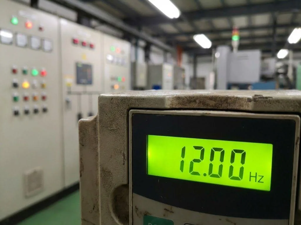
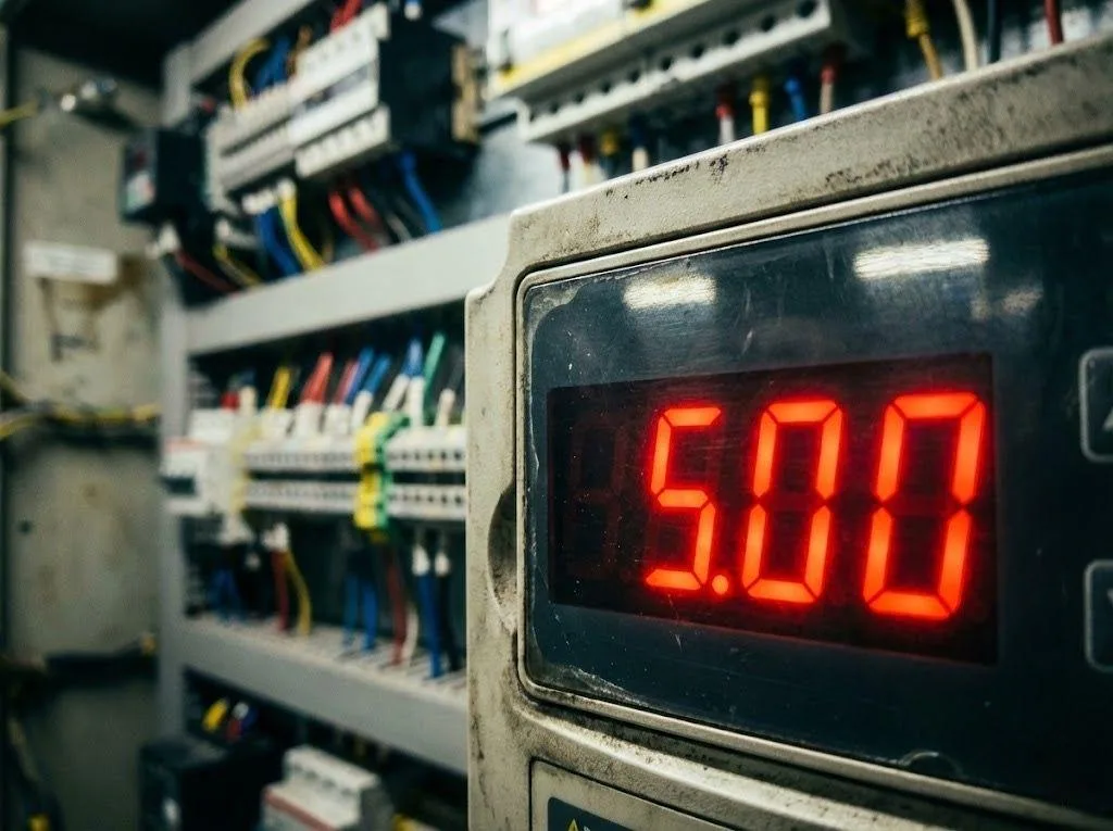
Restart the equipment and observe the current value displayed on the VFD control panel. If the displayed value is high, immediately use a clamp meter to measure the actual load current from the VFD to the motor. We need to compare the VFD display current with the actual current.
Note: The current measured by the clamp meter is typically slightly higher than the panel display value. This occurs because the clamp meter captures harmonics and interference, which is normal. We focus on consistency in magnitude.

Scenario 1: Panel Shows High Current, Actual Measurement Very Low
If you observe the panel displaying an extremely high current reading, but the clamp meter measures a very low current (e.g., only one-third of the rated current), this indicates the VFD is “lying.”
This indicates drift or failure within the VFD’s internal current detection sensor or control circuitry. For this type of VFD overcurrent fault at constant speed caused by hardware misjudgment, there is no need to inspect the external motor. It should be directly diagnosed as a VFD hardware failure, requiring contact with the manufacturer (e.g., Nanjing Oulu Electric) for repair.
Troubleshooting Three-Phase Voltage Imbalance and Drive Circuit
If the panel displays high values and actual current measurements are also high, this indicates that the VFD overcurrent fault at constant speed is caused by genuine overload. At this point, we need to analyze the three-phase voltage imbalance situation further.
Three-Phase Current Balance
If the three-phase currents are very high but highly balanced, this indicates the VFD itself is healthy.
Root Cause Identification:
- Process Issues: Overloaded or stalled load.
- Motor Issues: Undersized or mismatched motor (refer to EV510A Selection Guide).
- Mechanical Resistance: Abnormalities in the transmission mechanism.
In this scenario, use the process of elimination to inspect the motor and load; the VFD is not the cause.
Three-Phase Current Imbalance
This is the key focus when troubleshooting VFD overcurrent faults at constant speed. Disconnect the motor leads and directly measure the three-phase output voltage at the VFD terminals with a multimeter.
1.Output voltage is balanced, but load current is unbalanced
This is typically caused by “intermediate circuitry.” Check whether a circuit breaker or AC contactor is installed between the VFD and the motor.
Since the VFD outputs high-frequency PWM square waves rather than standard sine waves, the contactor’s contacts are prone to overheating and forming an oxide film under high-frequency pulses. This oxide film creates high-frequency resistance, leading to three-phase voltage imbalance and subsequently triggering the VFD overcurrent fault at constant speed.
Killer Tip: Don’t use a multimeter to measure contactor contact resistance (it won’t register). Instead, bypass the contactor directly and test the system. If the fault disappears, replace the contactor immediately.
2.Output voltage remains unbalanced after disconnecting the motor
This indicates an internal VFD issue. Typically, it’s not an IGBT failure (which usually triggers a short-circuit alarm), but rather an IGBT drive circuit failure.
When the drive voltage in one of the six channels drops, it increases the corresponding IGBT’s conduction voltage drop, causing output voltage imbalance. This constitutes a hardware defect; send the unit for repair.

Symptoms of Faulty VFD Encoder Coupling
If equipment exhibits noticeable discontinuous vibration accompanied by overcurrent during operation, focus on inspecting these two critical areas—often the hidden culprits behind VFD overcurrent faults at constant speed.
- Mechanical Jam: Poor bearing lubrication or mechanical locking can cause impact loads.
- Encoder Failure: This is practical experience often omitted from many expert textbooks. If the motor is equipped with an encoder, you must be able to recognize symptoms of bad VFD encoder coupling.
Fault Logic: If the coupling set screw is loose or the keyway is worn, the motor may rotate while the feedback signal momentarily drops out (missed steps), causing an encoder feedback error. For drives supporting closed-loop vector control (FVC), such as the EV510A, the system will interpret this as insufficient speed. The PID algorithm will then instantly output a massive current surge attempting to “catch up” to the speed target, triggering the VFD overcurrent fault at constant speed.
Microsecond Surge Current and Output Reactor
This represents the most severe fault condition: the panel displays a very low current (e.g., only 50% of rated current), yet the inverter frequently reports “VFD overcurrent fault constant speed.”
Even using a clamp meter won’t detect abnormalities, as this is a microsecond-level surge current.
Cause Analysis: Excessively long cables between the VFD and motor create significant distributed capacitance (coupling capacitance) between phases. Under the superimposed PWM harmonic voltages, this forms spike voltages that cause instantaneous charging and discharging of the distributed capacitance. This charging/discharging current is extremely brief yet has an extremely high peak, directly triggering the VFD’s hardware protection and causing the “VFD overcurrent fault constant speed” alarm.
Solution:
- Reduce carrier frequency: Refer to the EV200 manual or EV510A manual for parameter P0-15. Appropriately lower the carrier frequency (e.g., from 8kHz to 4kHz or lower). This effectively reduces harmonic voltages and leakage currents.
- Install an output reactor: Add an output reactor at the VFD output to suppress instantaneous spike currents, thereby eliminating the VFD overcurrent fault constant speed alarm.
Conclusion
Resolving the VFD overcurrent fault constant speed issue fundamentally involves a battle between ‘current authenticity’ and ‘interference sources’. From the simplest clamp meter measurements to identifying symptoms of poor VFD encoder coupling, and extending to the invisible suppression of surge currents, each step demands precise judgment.
For complex issues stemming from long cable runs or high harmonics, appropriately lowering the carrier frequency or adding an output reactor often yields remarkable results. If you require a more interference-resistant and stable drive solution during selection or replacement, we recommend consulting the technical manuals for our EV510A or EV200 series. Their built-in protection features—such as fast current limiting and overcurrent stall protection—significantly reduce the occurrence of such faults, ensuring continuous and stable production line operation.